13. FRONT & REAR FOG LAMP CIRCUIT
1) FOG LAMP CIRCUIT : HATCH BACK
a. CONNECTOR INFORMATION
CONNECTOR NO
(PIN NO, COLOR) |
CONNECTING WIRING HARNESS |
CONNECTOR POSITION |
| C102 (32 Pin, Gray) |
Front - Engine Fuse Block |
Engine Fuse Block |
| C103 (32 Pin, Brown) |
Front - Engine Fuse Block |
Engine Fuse Block |
| C201 (76 Pin, Black) |
I.P - I.P Fuse Block |
I.P Fuse Block |
| C203 (18 Pin, White) |
I.P - I.P Fuse Block |
I.P Fuse Block |
| C207 (12 Pin, Gray) |
Front - I.P |
Below I.P Fuse Block |
| C208 (22 Pin, Yellow) |
Front - I.P |
Front TCM |
| C209 (4 Pin, White)
|
Front - I.P |
Front TCM |
| C213 (24 Pin, White) |
I.P - Floor |
Under Left A Pillar |
| S202 |
I.P |
Behind Left Tie Bar |
| G101 |
Front |
Behind Right Headlamp |
| G102 |
Front |
Behind Left Headlamp |
| G201 |
I.P |
Upper Mirror Control Switch |
| G401 |
Floor |
Upper Left Back Shelf Panel |
b. CONNECTOR IDENTIFICATION SYMBOL & PIN NUMBER POSITION
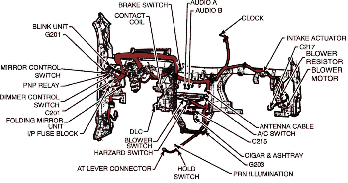
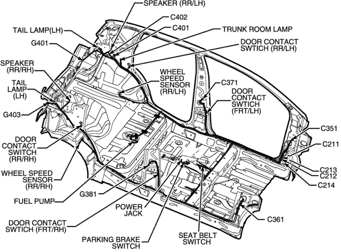
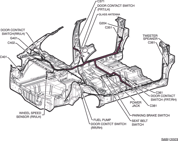
c. POSITION OF CONNECTORS AND GROUNDS
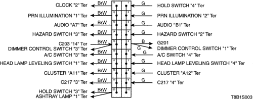
d. SPLICE PACK
S202
2) FOG LAMP CIRCUIT : NOTCH BACK
a. CONNECTOR INFORMATION
CONNECTOR NO
(PIN NO, COLOR) |
CONNECTING WIRING HARNESS |
CONNECTOR POSITION |
| C102 (32 Pin, Gray) |
Front - Engine Fuse Block |
Engine Fuse Block |
| C103 (32 Pin, Brown) |
Front - Engine Fuse Block |
Engine Fuse Block |
| C201 (76 Pin, Black) |
I.P - I.P Fuse Block |
I.P Fuse Block |
| C203 (18 Pin, White) |
I.P - I.P Fuse Block |
I.P Fuse Block |
| C207 (12 Pin, Gray) |
Front - I.P |
Below I.P Fuse Block |
| C208 (22 Pin, Yellow) |
Front - I.P |
Front TCM |
| C209 (4 Pin, White)
|
Front - I.P |
Front TCM |
| C213 (24 Pin, White) |
I.P - Floor |
Under Left A Pillar |
| S202 |
I.P |
Behind Left Tie Bar |
| G101 |
Front |
Behind Right Headlamp |
| G102 |
Front |
Behind Left Headlamp |
| G201 |
I.P |
Upper Mirror Control Switch |
| G401 |
Floor |
Upper Left Back Shelf Panel |
b. CONNECTOR IDENTIFICATION SYMBOL & PIN NUMBER POSITION
c. POSITION OF CONNECTORS AND GROUNDS
d. SPLICE PACK
S202
| © Copyright Chevrolet Europe. All rights reserved |