Aveo |
||||||||
|
||||||||
|
.
|
Application
|
Unit
|
Description
|
|
Camshaft
|
Lift - Intake
|
mm
|
46.3
|
|
Lift - Exhaust
|
mm
|
45.3
|
|
|
Bending
|
mm
|
0.04
|
|
|
Journal Outer Diameter : No.1
|
mm
|
Φ27.939-27.960
|
|
|
Journal Outer Diameter : No.2
|
mm
|
Φ27.939-27.960
|
|
|
Journal Outer Diameter : No.3
|
mm
|
Φ27.939-27.960
|
|
|
Journal Outer Diameter : No.4
|
mm
|
Φ27.939-27.960
|
|
|
Journal Outer Diameter : No.5
|
mm
|
Φ27.939-27.960
|
|
|
Trust Clearance(End Play)
|
mm
|
0.13-0.215
|
|
|
Cylinder Head
|
Journal Inner Diameter : No.1
|
mm
|
28.000-28.021
|
|
Journal Inner Diameter : No.2
|
mm
|
28.000-28.021
|
|
|
Journal Inner Diameter : No.3
|
mm
|
28.000-28.021
|
|
|
Journal Inner Diameter : No.4
|
mm
|
28.000-28.021
|
|
|
Journal Inner Diameter : No.5
|
mm
|
28.000-28.021
|
|
|
Journal Clearance
|
mm
|
0.04~0.082
|
|
|
Height
|
mm
|
135.55
|
|
|
Surface Flatness Deformation cover/Block
|
mm
|
0.02/50 / 0.025/150
|
|
|
Manifolds Surface Deformation
|
mm
|
0.05
|
|
|
Valve
|
Deviation
|
mm
|
0.03
|
|
Seat Inner Diameter - Intake
|
mm
|
30.7
|
|
|
Seat Inner Diameter - Exhaust
|
mm
|
27.2
|
|
|
Face Diameter - Intake
|
mm
|
Φ31.2+/-0.1
|
|
|
Face Diameter - Exhaust
|
mm
|
Φ27.5+/-0.1
|
|
|
GUIDE Inner Diameter - Intake
|
mm
|
Φ5.0-5.016
|
|
|
GUIDE Inner Diameter - Exhaust
|
mm
|
Φ5.0-5.016
|
|
|
Valve Stem Outer Diameter - Intake
|
mm
|
Φ4.965-4.980
|
|
|
Valve Stem Outer Diameter - Exhaust
|
mm
|
Φ4.950-4.965
|
|
|
Valve Length - Intake
|
mm
|
117.10 - 117.30
|
|
|
Valve Length - Exhaust
|
mm
|
116.16 - 116.36
|
|
|
Valve Spring - Straightness
|
°
|
Φ1.5
|
|
|
Valve Spring - Free Length
|
mm
|
41.6
|
|
|
Clearance (Intake)
|
mm
|
0.21-0.29 (nominal : 0.25 mm)
|
|
|
Clearance (Exhaust)
|
mm
|
0.27-0.35 (nominal : 0.25 mm)
|
|
|
Oil pump
|
Axial clearance
|
mm
|
0.02-0.058
|
|
Piston
|
Diameter
|
mm
|
77.9 (nominal)
|
|
Clearance
|
mm
|
0.030 ~ 0.060
|
|
|
Piston Ring
|
Groove Clearance - Top Ring
|
mm
|
0.04 ~ 0.08
|
|
Groove Clearance - 2nd Ring
|
mm
|
0.03 ~ 0.07
|
|
|
Groove Clearance - Oil Ring
|
mm
|
0.06 ~ 0.15
|
|
|
End Gap - Top Ring
|
mm
|
0.15 ~ 0.30
|
|
|
End Gap - 2nd Ring
|
mm
|
0.30 ~ 0.50
|
|
|
End Gap - Oil Ring
|
mm
|
0.20 ~ 0.70
|
|
|
Piston Pin
|
Diameter
|
mm
|
19.000 ~ 19.005
|
|
Length
|
mm
|
49.84 (-0.25~0.0)
|
|
|
Clearance
|
mm
|
0.007 ~ 0.020
|
|
|
Connecting Rod
|
Thrust Clearance(End Play)
|
mm
|
0.07 ~ 0.242
|
|
Width
|
mm
|
21.839 ~ 21.890
|
|
|
Diameter - Piston Pin
|
mm
|
19.012 ~ 19.020
|
|
|
Diameter - Crankshaft
|
mm
|
46.000 ~ 46.012
|
|
|
Bending
|
mm
|
0.04
|
|
|
Twist
|
mm
|
0.016
|
|
|
Journal Bearing Oil Clearance
|
mm
|
0.019 ~ 0.063
|
|
|
Crankshaft
|
Thrust Clearance(End Play)
|
mm
|
0.1~0.202
|
|
Journal Outer Diameter
|
mm
|
main : Φ54.980~54.997
pin : Φ42.971~42.987
|
|
|
Journal Bearing Oil Clearance
|
mm
|
main : Φ0.0155~0.047
pin : Φ0.019~0.067
|
|
|
Bending
|
mm
|
0.03
|
|
|
Cylinder Block
|
Diameter
|
mm
|
77.9
|
|
Deck Surface Flatness
|
mm
|
0.025/65
|
|
|
Cylindricity
|
mm
|
0.0065
|
|
Application
|
N•m
|
Lb-Ft
|
Lb-In
|
|
Accessory Belt Tensioner Bolt
|
50
|
36.8
|
-
|
|
Alternator B+ Tightening Nut
|
15
|
11
|
-
|
|
Camshaft Adjuster Bolts
|
65+120°+15°
|
47.9+120°+15°
|
-
|
|
Camshaft Bearing Cap Bolts
|
8
|
-
|
70.8
|
|
Camshaft Sprocket Bolt Cap
|
50
|
36.8
|
-
|
|
Camshaft Sprocket Bolts
|
65
|
47.9
|
-
|
|
Closure Bolt
|
15
|
11
|
-
|
|
Connecting-Rod Caps Bolts
|
35+45°+15°
|
25.8+45°+15°
|
-
|
|
Coolant Pipe to Coolant Distributor Case Bolts
|
8
|
-
|
70.8
|
|
Crankshaft Cap Bolts
|
50+50°
|
36.8+50°
|
-
|
|
Crankshaft Pulley Bolt
|
25
|
18.4
|
-
|
|
Cylinder Head Bolts
|
25+90°+90°+90°+45°
|
18.4+90°+90°+90°+45°
|
-
|
|
Cylinder Head Cover Bolts
|
8
|
-
|
70.8
|
|
Engine Front Cover Assembly Bolts
|
20
|
14.7
|
-
|
|
Engine Mount Bolts and Nuts
|
55
|
40.5
|
-
|
|
Engine Mount Bracket Bolt
|
65
|
47.9
|
-
|
|
Exhaust Manifold Lower Bracket Bolts
|
20
|
14.7
|
-
|
|
Exhaust Manifold Nuts
|
20
|
14.7
|
-
|
|
Flywheel(Flexible Plate) Bolts
|
35+30°+15°
|
25.8+30°+15°
|
-
|
|
Ground Tightening Nut
|
12
|
8.8
|
-
|
|
Heat Exchanger Bolts
|
8
|
-
|
70.8
|
|
Heat Shield Bolts
|
8
|
-
|
70.8
|
|
Ignition Coil Bolt
|
8
|
-
|
70.8
|
|
Indicator Tube Tightening Bolt
|
10
|
7.3
|
-
|
|
Intake Manifold Bolts
|
20
|
14.7
|
-
|
|
Intake Manifold Lower Bracket Bolt
|
8
|
-
|
70.8
|
|
Oil Cooler Tightening Bolts
|
25
|
18.4
|
-
|
|
Oil Pan Baffle Bolts
|
10
|
7.3
|
-
|
|
Oil Pan Bolts
|
14
|
10.3
|
-
|
|
Oil Pan-to-Transmission Bolts
|
40
|
29.5
|
-
|
|
Reaction Rod-to-Bracket Bolt and Nut
|
80
|
59
|
-
|
|
Reaction Rod-to-Crossmember Bolts
|
55
|
40.5
|
-
|
|
Spark Plug
|
25
|
18.4
|
-
|
|
Starter Solenoid B+ Tightening Nut
|
10.5
|
7.7
|
-
|
|
Starter Solenoid Ground Tightening Nut
|
38
|
28
|
-
|
|
Timing Belt Idler Bolt
|
50
|
36.8
|
-
|
|
Timing Belt Lower Cover Bolts
|
6
|
-
|
53.1
|
|
Timing Belt Rear Cover Bolts
|
6
|
-
|
53.1
|
|
Timing Belt Tensioner Bolt
|
55
|
40.6
|
-
|
|
Timing Belt Upper Cover Bolts
|
4
|
-
|
35.4
|
|
Transmission Tightening Bolt
|
60
|
44.2
|
-
|
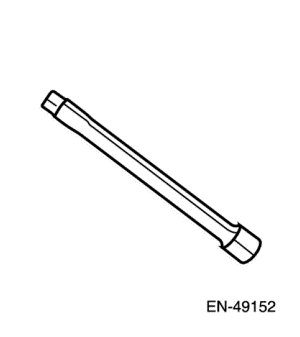 |
EN-49152
Oil Pan Bolt Remover/Installer
|
 |
EN-49153
Cylinder Pressure Adapter
|
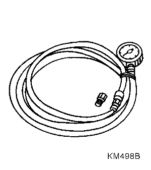 |
KM-498-B
Pressure Gauge
|
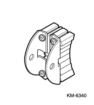 |
KM-6340
Locking Tool
|
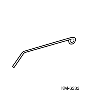 |
KM-6333
Fixing Rod
|
 |
KM-422
Installer
|
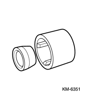 |
KM-6351
Assembly Sleeves
|
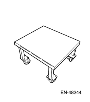 |
EN-48244
Engine Assembly Remove/Install Pallet Supporter
|
 |
EN-49155
Valve Spring Compressing Adapter
|
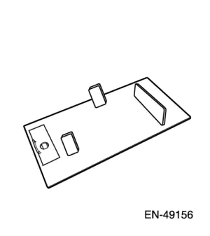 |
EN-49156
Engine Assembly Remove/Install Pallet
|
 |
EN-49153
Piston Installer(1.6L ONLY)
|
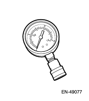 |
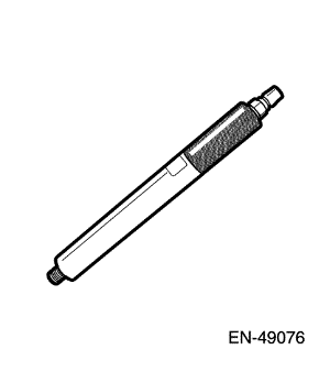
EN-49077
Compression Pressure Gauge
|
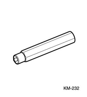 |
KM-232
Adapter
|
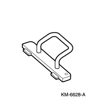 |
KM-6628-A
Locking Tool
|
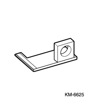 |
KM-6625
Flywheel Locking Device
|
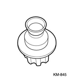 |
KM-845
Suction Device
|
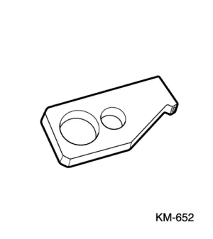 |
KM-652
Flywheel Locking Device
|
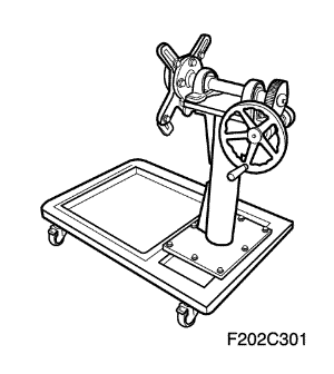 |
F202C301
Engine Overhaul Stand
|
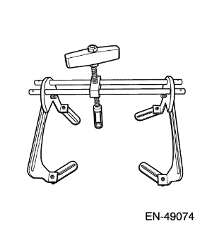 |
EN-49074
Universal Valve Spring Compressor
|
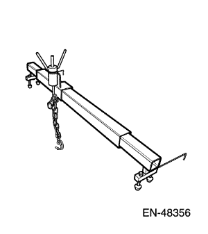 |
EN-48356
Engine Fixture
|
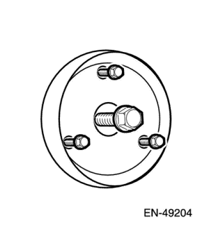 |
EN-49204
Crankshaft Rear Oil Seal Remover
|
Condition
|
Action
|
|
Abnormalities (severe cracking, bumps or missing areas) in the accessory drive belt.
Also worn, damaged, or misaligned accessory drive components or excessive pulley runout.
|
Abnormalities in the accessory drive belt and/or components may cause engine RPM variations, noises similar to a faulty lower engine and also lead to a misfire condition. A misfire code may be present without an actual misfire condition.
|
|
Loose and/or damaged crankshaft pulley
|
A misfire code may be present without an actual misfire condition.
|
|
Loose torque converter bolts
|
A misfire code may be present without an actual misfire condition.
|
|
Loose and/or damaged flywheel
|
A misfire code may be present without an actual misfire condition.
|
|
Restricted exhaust system
|
A severe restriction in the exhaust flow can cause significant loss of engine performance and may set a misfire code. Possible causes of restrictions include collapsed or dented pipes, plugged mufflers and/or catalytic converters.
Repair or replace all damaged components.
|
|
Air in fuel system
|
|
|
Bent and/or worn valve bridge and finger-follower.
|
|
|
Sticking valve
|
Carbon on the valve stem or valve seat may cause the valve to stick.
|
|
Damaged or misaligned timing gears
|
|
|
Worn or faulty camshaft lobes
|
|
|
Excessive piston-to-cylinder bore clearance
|
|
|
Faulty cylinder head gaskets and/or cracking or other damage to the cylinder heads and engine block cooling system passages. (Coolant consumption may or may not cause the engine to overheat.)
|
|
Condition
|
Action
|
|
Abnormalities (severe cracking, bumps or missing areas) in the accessory drive belt.
|
Abnormalities in the accessory drive belt and/or components may cause engine RPM variations, noises similar to a faulty lower engine and also lead to a misfire condition. A misfire code may be present without an actual misfire condition.
|
|
Worn, damaged, or misaligned accessory drive components or excessive pulley runout
|
A misfire code may be present without an actual misfire condition.
|
|
Loose and/or damaged crankshaft pulley
|
A misfire code may be present without an actual misfire condition.
|
|
Loose torque converter bolts
|
A misfire code may be present without an actual misfire condition.
|
|
Loose and/or damaged flywheel
|
A misfire code may be present without an actual misfire condition.
|
|
Excessive piston-to-cylinder bore clearance
|
|
|
Excessive crankshaft thrust bearing clearance
|
Severely worn thrust surfaces on the crankshaft and/or thrust bearing may permit for and aft movement of the crankshaft and create a misfire code without an actual misfire condition.
|
Condition
|
Action
|
|
Loose, worn or damaged valve bridge and finger-follower
|
|
|
Broken valve springs
|
|
|
Sticking valve
|
Carbon on the valve stem or valve seat may cause the valve to stick.
|
|
Worn or faulty camshaft lobes
|
|
Inspection
|
Action
|
|
Definition : Base engine misfire with coolant consumption
|
|
|
Preliminary Inspection
|
Verify that there are no external coolant leaks. Refer to Section1D1, Engine Cooling – 2.0Diesel.
|
|
Isolate Affected Cylinders
|
|
|
EGR System Inspection
|
|
|
Cylinder Head Gasket Leakage
|
|
|
Cylinder Head or Engine Block Damage
|
|
Condition
|
Action
|
|
Worn valve guides
|
|
|
Worn valve stem oil seals
|
|
|
Excessive piston-to-cylinder bore clearance
|
|
Condition
|
Action
|
|
Incorrect oil viscosity
|
|
|
Excessive piston-to-cylinder bore clearance
|
|
Condition
|
Action
|
|
Low oil pressure
|
Insufficient or poor oil supply to valve train.
|
|
Improper lubrication to the valve finger-follower
|
|
|
Worn or damaged valve finger-follower
|
|
|
Sticking valve
|
Carbon on the valve stem or valve seat may cause the valve to stick.
|
|
Worn or faulty camshaft lobes
|
|
|
Damaged or misaligned timing gears
|
|
Condition
|
Action
|
|
Worn accessory drive components (abnormalities such as severe cracking, bumps or missing areas in the accessory drive belt and/or misalignment of the system components.)
|
|
|
Low oil pressure
|
Insufficient or poor oil supply to crankshaft and connecting rod bearings.
|
|
Leaking and/or sticking fuel injection nozzle (A stuck fuel injection nozzle can cause a noise similar to a damaged piston, rod or rod bearing.)
|
|
|
Loose and/or damaged crankshaft pulley
|
|
|
Loose torque converter bolts
|
|
|
Loose and/or damaged flywheel
|
|
|
Excessive piston pin-to-bore clearance
|
|
|
Misaligned or bent connecting rod
|
|
|
Excessive connecting rod bearing clearance
|
|
|
Excessive crankshaft bearing clearance
|
|
Cause
|
Correction
|
|
Low oil pressure
|
Insufficient or poor oil supply to components.
|
|
Loose torque converter bolts
|
|
|
Loose and/or damaged flywheel
|
|
|
Excessive piston-to-cylinder bore clearance
|
|
|
Excessive crankshaft thrust bearing clearance
|
|
|
Excessive crankshaft bearing clearance
|
|
Cause
|
Correction
|
|
Seized accessory drive system component
|
|
|
Hydraulically locked cylinder
|
|
|
Seized automatic transmission torque converter
|
|
|
Seized manual transmission
|
Refer to Unit Repair Manual - Manual Transmission.
|
|
Material in cylinder :
|
|
|
Seized crankshaft or connecting rod bearings
|
|
|
Bent or broken connecting rod
|
|
|
Broken crankshaft
|
|
Inspection
|
Action
|
|
Definition : Excessive white smoke and/or coolant type odor coming from the exhaust pipe may indicate coolant in the combustion chamber. Low coolant levels, an inoperative cooling fan, or a faulty thermostat may lead to an "overtemperature" condition which may cause engine component damage.
|
|
|
Preliminary Inspection
|
Verify that there are no external coolant leaks. Refer to Section 1D, Engine Cooling.
|
|
Isolate Affected Cylinders
|
|
|
EGR System Inspection
|
|
|
Cylinder Head Gasket Leakage
|
|
|
Cylinder Head or Engine Block Damage
|
|
Cause
|
Correction
|
|
Definition : Foamy or discolored oil or an engine oil "overfill" condition may indicate coolant entering the engine crankcase. Low coolant levels, an inoperative cooling fan, or a faulty thermostat may lead to an "overtemperature" condition which may cause engine component damage. Contaminated engine oil and oil filter should be changed.
|
|
|
Faulty cylinder head gasket
|
Replace the head gasket and components as required. Refer to Section 1C2, Engine Mechanical – 1.4 DOHC - G14D.
|
|
Warped cylinder head
|
Replace the cylinder head gasket. Refer to Section 1C2, Engine Mechanical – 1.4 DOHC - G14D.
|
|
Cracked cylinder head
|
Replace the cylinder head and gasket.
|
|
Cracked engine block
|
Replace the components as required.
|
|
Cylinder head, block, or manifold porosity
|
Replace the components as required.
|
|
Leaking engine oil cooler
|
Replace components as required.
|
| Step | Action | Value(s) | Yes | No |
| 1 |
Did you review the information provided in Symptoms, and perform the required inspections.
|
-
|
Go to Step 2
|
Go to Symptoms
|
| 2 |
Confirm the customer complaint. Is there a chirping noise?
|
-
|
Go to Step 3
|
Refer to Diagnostic Aids in this Section
|
| 3 |
Does the chirping noise still exist?
|
-
|
Accessory drive system OK.
Go to Symptoms, and restart the diagnosis of the noise
|
Go to Step 4
|
| 4 |
Inspect for severe pilling, i.e. in excess of 33% of the belt groove depth.
Do the belt grooves have pilling?
|
-
|
Go to Step 5
|
Go to Step 6
|
| 5 |
Clean the drive belt pulleys with a wire brush.
Are the belt pulleys clean?
|
-
|
Go to Step 15
|
Go to Step 6
|
| 6 |
Inspect for misalignment of the pulleys.
Are the pulleys misaligned?
|
-
|
Go to Step 7
|
Go to Step 8
|
| 7 |
Replace or repair misaligned pulleys.
Did you complete the repair?
|
-
|
Go to Step 15
|
-
|
| 8 |
Inspect for any bent or damaged accessory drive component mounting brackets.
Did you find any bent or damaged brackets?
|
-
|
Go to Step 9
|
Go to Step 10
|
| 9 |
Replace or repair any bent or damaged Brackets.
Did you complete the repairs?
|
-
|
Go to Step 15
|
-
|
| 10 |
Inspect for missing, loose or incorrect fasteners.
Did you find any missing, loose or incorrect fasteners?
|
-
|
Go to Step 11
|
Go to Step 12
|
| 11 |
Tighten any loose fasteners to the torque specification.
Replace any incorrect or missing fasteners.
Did you complete the repairs?
|
-
|
Go to Step 15
|
-
|
| 12 |
Inspect for a bent pulley.
Did you find any bent pulleys?
|
-
|
Go to Step 13
|
Go to Step 14
|
| 13 |
Replace bent pulleys as required.
Did you complete the repair?
|
-
|
Go to Step 15
|
-
|
| 14 |
Replace the accessory drive belt, refer to Section 1C2, Engine Mechanical – 1.4 DOHC - G14D.
Did you complete the repair?
|
-
|
Go to Step 15
|
-
|
| 15 |
Reinstall the accessory drive belt and operate the system to confirm the repair.
Did you correct the chirp noise?
|
-
|
Accessory drive system OK
|
Go to Symptoms,
and restart the diagnosis
|
| Step | Action | Value(s) | Yes | No |
| 1 |
Did you review the information provided in Symptoms, and perform the required inspections.
|
-
|
Go to Step 2
|
Go to Symptoms
|
| 2 |
Confirm the customer complaint. Is there a squealing noise?
|
-
|
Go to Step 3
|
Refer to Diagnostic Aids in this Section
|
| 3 |
Does the squealing noise still exist?
|
-
|
Accessory drive system OK.
Go to Symptoms, and restart the diagnosis of the noise
|
Go to Step 4
|
| 4 |
Inspect the accessory drive components for a seized bearing and general malfunctions.
Did you find and correct any seized bearings or general malfunctions in the accessory drive system?
|
-
|
Go to Step 9
|
Go to Step 5
|
| 5 |
Test the accessory drive belt tensioner for correct operation, refer to Drive Belt Tensioner Diagnosis.
Did you find and repair any problems with the tensioner?
|
-
|
Go to Step 9
|
Go to Step 6
|
| 6 |
Inspect the accessory drive belt is the correct length.
Did you find and repair any problems with the drive belt length?
|
-
|
Go to Step 9
|
Go to Step 7
|
| 7 |
Inspect the accessory drive pulleys for misalignment.
Did you find and correct any misaligned accessory drive pulleys?
|
-
|
Go to Step 9
|
Go to Step 8
|
| 8 |
Check the accessory drive pulleys are the correct size.
Did you find and replace any incorrect pulleys?
|
-
|
Go to Step 9
|
Refer to Diagnostic Aids in this Section
|
| 9 |
Reinstall the accessory drive belt and operate the system to confirm the repair.
Did you correct the squeal noise?
|
-
|
Accessory drive system OK
|
Go to Symptoms,
and restart the diagnosis
|
| Step | Action | Value(s) | Yes | No |
| 1 |
Did you review the information provided in Symptoms, and perform the required inspections.
|
-
|
Go to Step 2
|
Go to Symptoms
|
| 2 |
Confirm the customer complaint. Is there a whining noise?
|
-
|
Go to Step 3
|
Refer to Diagnostic Aids in this Section
|
| 3 |
Does the whining noise still exist?
|
-
|
Accessory drive system OK.
Go to Symptoms, and restart the diagnosis
|
Go to Step 4
|
| 4 |
Inspect the accessory drive components for a faulty or seized bearings and general malfunctions.
Did you find and correct any faulty/seized bearings or general malfunctions in the accessory drive system?
|
-
|
Go to Step 5
|
Refer to Diagnostic Aids in this Section
|
| 5 |
Reinstall the accessory drive belt and operate the system to confirm the repair.
Did you correct the whine?
|
-
|
Accessory drive system OK
|
Go to Symptoms,
and restart the diagnosis
|
| Step | Action | Value(s) | Yes | No |
| 1 |
Did you review the information provided in Symptoms, and perform the required inspections.
|
-
|
Go to Step 2
|
Go to Symptoms
|
| 2 |
Confirm the customer complaint. Is there a rumbling noise?
|
-
|
Go to Step 3
|
Refer to Diagnostic Aids in this Section
|
| 3 |
Does the rumbling noise still exist?
|
-
|
Accessory drive system OK.
Go to Symptoms, and restart the diagnosis
|
Go to Step 4
|
| 4 |
Inspect the accessory drive belt for damage, separation or sections of missing ribs.
Did you find any damaged, separated or missing ribs?
|
-
|
Go to Step 7
|
Go to Step 5
|
| 5 |
Inspect the accessory drive belt for severe pilling (exceeding 33% of the belt groove depth).
Did you find sever pilling?
|
-
|
Go to Step 6
|
Go to Step 5
|
| 6 |
Clean the drive belt using a suitable wire brush and reinstall to the engine, refer to Section 1B, Engine Mechanical – 2.0 Diesel.
Did you complete the repairs?
|
-
|
Go to Step 8
|
-
|
| 7 |
Install a new accessory drive belt, refer to Section 1C2, Engine Mechanical – 1.4 DOHC - G14D.
Did you replace the accessory drive belt?
|
-
|
Go to Step 8
|
-
|
| 8 |
If required, reinstall the accessory drive belt and operate the system to confirm the repair.
Did you correct the rumbling noise?
|
-
|
Accessory drive system OK
|
Go to Symptoms,
and restart the diagnosis
|
| Step | Action | Value(s) | Yes | No |
| 1 |
Did you review the information provided in Symptoms, and perform the required inspections.
|
-
|
Go to Step 2
|
Go to Symptoms
|
| 2 |
Confirm the customer complaint. Is there a rumbling noise?
|
-
|
Go to Step 3
|
Refer to Diagnostic Aids in this Section
|
| 3 |
Does the vibration noise still exist?
|
-
|
Accessory drive system OK.
Go to Symptoms, and restart the diagnosis
|
Go to Step 4
|
| 4 |
Inspect the accessory drive belt for damage, wear, debris build-up or sections of missing ribs.
Did you find any damage, wear, debris build-up or missing ribs?
|
-
|
Go to Step 5
|
Go to Step 6
|
| 5 |
Install a new accessory drive belt, refer to Section 1C2, Engine Mechanical – 1.4 DOHC - G14D.
Did you replace the accessory drive belt?
|
-
|
Go to Step 9
|
-
|
| 6 |
Inspect for incorrect, loose, missing or damaged fasteners.
Did you find any incorrect, loose, missing or damaged fasteners?
|
-
|
Go to Step 7
|
Go to Step 8
|
| 7 |
Tighten any loose fasteners to the correct torque specification.
Replace any incorrect or missing fasteners.
Did you complete the repairs?
|
-
|
Go to Step 9
|
-
|
| 8 |
Inspect for bent, cracked or damaged accessory drive component mounting brackets.
Did you find and repair any bent brackets?
|
-
|
Go to Step 9
|
Refer to Diagnostic Aids in this Section
|
| 9 |
If required, reinstall the accessory drive belt and operate the system to confirm the repair.
Did you correct the vibration?
|
-
|
Accessory drive system OK
|
Refer to Diagnostic Aids in this Section
|
| Step | Action | Value(s) | Yes | No |
| 1 |
Did you review the information provided in Symptoms, and perform the required inspections.
|
-
|
Go to Step 2
|
Go to Symptoms
|
| 2 |
Inspect for a damaged accessory drive belt.
Did you find any damage on the drive belt?
|
-
|
Go to Step 3
|
Go to Step 4
|
| 3 |
Install a new accessory drive belt, refer to Section 1C2, Engine Mechanical – 1.4 DOHC - G14D.
Does the drive belt continue to fall off?
|
-
|
Go to Step 4
|
Go to Step 12
|
| 4 |
Inspect the accessory drive system pulleys for misalignment.
Did you find and repair any misaligned drive system pulleys?
|
-
|
Go to Step 12
|
Go to Step 5
|
| 5 |
Inspect for a dented or cracked accessory drive system pulley.
Did you find and repair any dented or cracked drive system?
|
-
|
Go to Step 12
|
Go to Step 6
|
| 6 |
Inspect for bent accessory drive component mounting brackets.
Did you find and repair any bent mounting brackets?
|
-
|
Go to Step 12
|
Go to Step 7
|
| 7 |
Inspect for incorrect, loose, missing or damaged fasteners.
Did you find any incorrect, loose, missing or damaged fasteners?
|
-
|
Go to Step 8
|
Go to Step 9
|
| 8 |
Tighten any loose fasteners to the correct torque specification.
Replace any incorrect or missing fasteners.
Does the drive belt continue to fall off?
|
-
|
Go to Step 9
|
Go to Step 12
|
| 9 |
Test the accessory drive belt tensioner for correct operation, refer to Section 1C2, Engine Mechanical – 1.4 DOHC - G14D.
Did you accessory drive belt tensioner operate correctly?
|
-
|
Go to Step 11
|
Go to Step 10
|
| 10 |
Replace the drive belt tensioner, refer to Section 1C2, Engine Mechanical – 1.4 DOHC - G14D.
Does the drive belt continue to fall off?
|
-
|
Go to Step 11
|
Go to Step 12
|
| 11 |
Inspect for a failed drive belt idler and drive belt tensioner bearings.
Did you find and repair any failed bearings?
|
-
|
Go to Step 12
|
Refer to Diagnostic Aids in this Section
|
| 12 |
If required, reinstall the accessory drive belt and operate the system to confirm the repair.
Does the drive belt continue to fall off?
|
-
|
Go to Step 2
|
Accessory drive system OK
|
| Step | Action | Value(s) | Yes | No |
| 1 |
Did you review the information provided in Symptoms, and perform the required inspections.
|
-
|
Go to Step 2
|
Go to Symptoms
|
| 2 |
Inspect the accessory drive belt for correct installation.
Is the drive belt installed correctly?
|
-
|
Go to Step 5
|
Go to Step 3
|
| 3 |
Ensure that the drive belt is the correct one for the application.
Is the correct drive belt installed?
|
-
|
Go to Step 5
|
Go to Step 4
|
| 4 |
Is the drive belt contacting any engine or body components with the engine running?
|
-
|
Go to Step 6
|
Refer to Diagnostic Aids in this Section
|
| 5 |
Install a new accessory drive belt, refer to Section 1C2, Engine Mechanical – 1.4 DOHC - G14D.
Did you replace the accessory drive belt?
|
-
|
Go to Step 6
|
-
|
| 6 |
If required, reinstall the accessory drive belt and operate the system to confirm the repair.
Did you correct the excessive wear?
|
-
|
Accessory drive system OK
|
Go to Step 2
|
| © Copyright Chevrolet Europe. All rights reserved |


