To the top of the document
Aveo
To Previous Page To Next Page
GMDE Start Page Load static TOC Load dynamic TOC Help?

SECTION 1E

ENGINE ELECTRICAL

Caution : Disconnect the negative battery cable before removing or installing any electrical unit or when a tool or equipment could easily come in contact with exposed electrical terminals. Disconnecting this cable will help prevent personal injury and damage to the vehicle. The ignition must also be in LOCK unless otherwise noted.

SPECIFICATIONS

Starter Specifications

Description
Unit
1.2 DOHC (B12D)
1.4 DOHC - G14D
Type
-
Permanent Magnet Straight Drive
PG 260C (G3)
Output (Capacity)
kW
0.8
1.2
Drive Pinion Speed (No Load Test @ 12 volts Condition)
RPM
4,845 Min
2,800 Min
Brushes length
mm (in.)
11.4 (0.448)
8.25 (0.325)

Generator Specifications

Description
Unit
1.2 DOHC (B12D)
1.4 DOHC - G14D
Type
-
NP08
NP/OH
System Voltage
V
12
12
Brushes length
mm (in.)
18.8 (0.74)
18.8 (0.740)
Output (Capacity)
A
80
95

Battery Specifications

Description
Unit
1.2 DOHC (B12D)
1.4 DOHC - G14D
Capacity
AH
45
50
Cold Cranks Amps
CCA
430
550
Reserve Capacity Minimum
min
80
90
Load Test
amps
200
270
Minimum Voltage:
-
-
-
9.6
V
70°F (21°C) and above
9.5
V
60°F (15.6°C)
60°F (15.6°C)
9.4
V
50°F (10°C)
50°F (10°C)
9.3
V
40°F (4.4°C)
40°F (4.4°C)
9.1
V
30°F (-1.1°C)
30°F (-1.1°C)
8.9
V
20°F (-6.7°C)
20°F (-6.7°C)
8.7
V
10°F (-12.2°C)
10°F (-12.2°C)
8.5
V
0°F (-17.8°C)
0°F (-17.8°C)

Fastener Tightening Specifications

Application
N•m
Lb-Ft
Lb-In
Battery Cable Nuts
4.5
-
40
.
Battery Carrier Tray Lower Bolts
20
15
-
Battery Carrier Tray Upper Bolts
20
15
-
Battery Retainer Clamp-to-Battery Rod Nuts
4
-
35
Fuel Rail Retaining Bolts
20
15
-
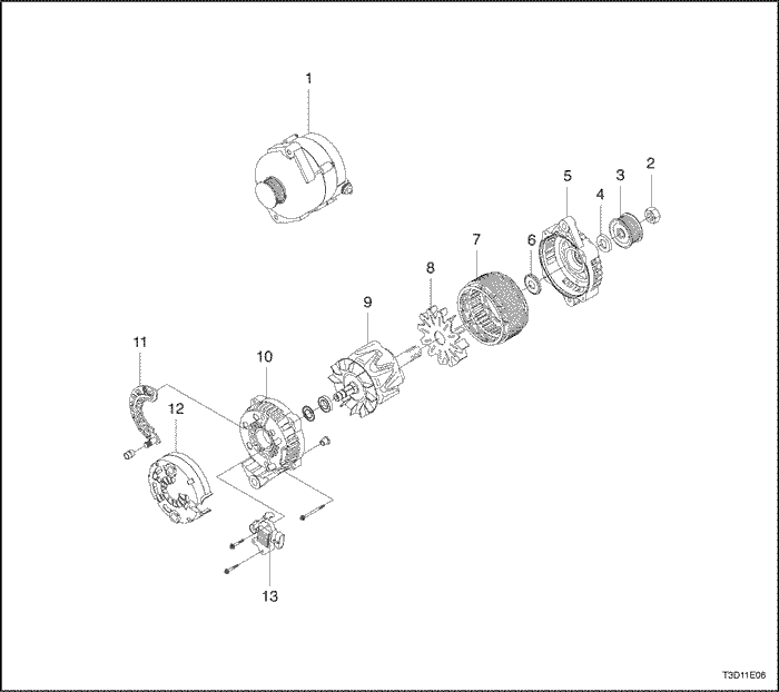
Generator Battery Lead Nut
15
11
-
Generator Drive End Bearing Nut
81
60
-
Generator Lower Bracket-to-Generator Nuts
25
18
-
Generator Pulley Retaining Nut
95
70
-
Generator Rear Cover Retaining Nut (B12D)
16.5
12.1
-
Generator Rear Cover Retaining Nut (G14D)
18.5
13.6
-
Generator Retaining Bolt/Nut (B12D)
25
18.4
-
Generator Retaining Bolt/Nut (G14D)
35
25.8
-
Generator Shackle Bracket Bolt
25
18
-
Generator Through-Bolts (G12D)
4.75
3.5
-
Generator Through-Bolts (G14D)
4.75
3.5
-
Starter Field Coil Connector Nut
8
-
71
Starter Mounting Bolts (G12D)
23
17
-
Starter Mounting Bolts (G14D)
25
18.4
-
Starter Solenoid Nuts
10.5
7.7
-

SCHEMATIC AND ROUTING DIAGRAMS

Starting & Charging System


T8B12E03
Display graphicTranslations of text in graphics


COMPONENT LOCATOR

Starting System - 1.2 DOHC -


M3C11E01
Display graphicTranslations of text in graphics


  1. Starter Motor Assembly
  2. Starter Solenoid Assembly
  3. Starter Housing
  4. Shift Lever
  5. Armature Set
  6. Armature
  7. Pinion Gear Assembly
  8. Ring Set
  9. Field Frame Assembly
  10. Brush Holder Assembly
  11. Contact End Frame Assembly
  12. Starter Through - Bolts

Starting System - 1.4 DOHC -


T3D11E05
Display graphicTranslations of text in graphics


  1. Starter Motor Assembly
  2. Starter Solenoid Assembly
  3. Starter Housing
  4. Shift Lever
  5. Armature Set
  6. Armature
  7. Pinion Gear Assembly
  8. Ring Set
  9. Field Frame Assembly
  10. Brush Holder Assembly
  11. Contact End Frame Assembly
  12. Starter Through - Bolts

Charging System - 1.2 DOHC -


T3D11E02
Display graphicTranslations of text in graphics


  1. Generator Assembly
  2. Generator Shackle
  3. Generator Drive End Nut
  4. Generator Pully
  5. Generator Collar (Large)
  6. Generator Front Bracket
  7. Front Bearing
  8. Bearing Spot Plate
  9. Generator Collar (Small)
  10. Generator Rotor Assembly
  11. Rear Bearing
  12. Generator Stator Assembly
  13. Rectifier Assembly
  14. Voltage Regulator/Brush Holder Assembly
  15. Generator Rear Bracket
  16. Battery Positive Terminal Nut
  17. Through Bolt

Charging System - 1.4 DOHC -


T3D11E06
Display graphicTranslations of text in graphics


  1. Generator Assembly
  2. Generator Drive End Nut
  3. Generator Pully
  4. Generator Collar
  5. Generator Front Bracket
  6. Front Bearing
  7. Generator Stator Assembly
  8. Fan
  9. Generator Rotor Assembly
  10. Generator Rear Bracket
  11. Rectifier Assembly
  12. Cover
  13. Voltage Regulator/Brush Holder Assembly

DIAGNOSIS

No Crank

Step Action Value(s) Yes No
1
  1. Press the clutch pedal completely down.
  2. Turn the key to START.
Does the vehicle start?
-
System OK
Go to Step 2
2
  1. Disconnect the clutch pedal position switch wires.
  2. Check for continuity between the switch terminals when the clutch pedal switch is pushed to the ON position.
Does the ohmmeter indicate the value specified?
-
Go to Step 4
Go to Step 3
3
Replace the clutch pedal position switch.
Does the vehicle start?
-
System OK
Go to Step 4
4
  1. Turn the headlamps ON.
  2. Turn the dome lamps ON.
  3. Turn the key to START.
Do the lights dim or go out?
-
Go to Step 5
Go to Step 11
5
Check the battery state of charge.
Is the green eye showing from the built-in hydrometer?
-
Go to Step 6
Go to "Charging Procedure"
6
  1. Connect the voltmeter positive lead to the positive battery terminal.
  2. Connect the voltmeter negative lead to the negative battery terminal.
  3. Turn the ignition to START.
Does the voltmeter indicate the value specified?
< 9.6 v
Go to "Charging Procedure"
Go to Step 7
7
  1. Connect the voltmeter negative lead to the negative battery terminal.
  2. Connect the voltmeter positive lead to the engine block.
  3. Place the ignition in the START position.
Is the repair complete?
> 0.5 v
Go to Step 8
Go to Step 9
8
  1. Clean and tighten the negative battery cable connections both at the battery end and at the ground end.
  2. Replace the cable if needed.
Is the repair complete?
-
System OK
-
9
  1. Connect the voltmeter positive lead to the starter "B" terminal.
  2. Connect the voltmeter negative lead to the negative battery terminal.
  3. Check the cranking voltage.
Does the voltmeter indicate the value specified?
< 9 v
Go to Step 10
Go to Step 16
10
Clean, tighten, or replace the positive battery cable.
Is the repair complete?
-
System OK
-
11
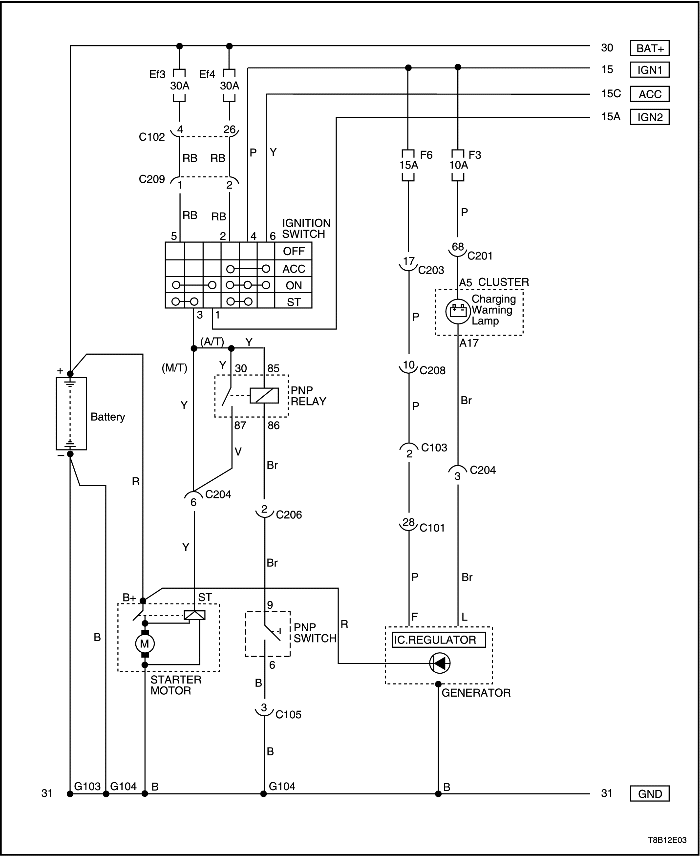
Check system fuse EF3 in the engine fuse block.
Is fuse EF3 blown?
-
Go to Step 12
Go to Step 13
12
Replace system fuse EF3.
Is the repair complete?
-
System OK
-
13
Check the connection at the starter "S" terminal.
Is the connection in good condition?
-
Go to Step 15
Go to Step 14
14
Repair the starter "S" terminal.
Is the repair complete?
-
System OK
-
15
  1. Connect the voltmeter positive lead to the starter "S" terminal.
  2. Connect the voltmeter negative lead to the negative battery terminal.
  3. Place the ignition in the START position.
  4. Read the voltage present at the "S" terminal.
Does the voltmeter indicate the specified value?
> 7 v
Go to Step 16
Go to Step 17
16
Repair or replace the starter.
Is the repair complete?
-
System OK
-
17
Turn on the heater blower.
Does the blower operate?
-
Go to Step 27
Go to Step 18
18
  1. Disconnect connector C204.
  2. Connect the voltmeter positive lead to terminal 1 of connector C204.
  3. Connect the voltmeter negative terminal to ground.
Does the voltmeter indicate the specified value?
12 v
Go to Step 20
Go to Step 19
19
Repair the open in the RED/WHT wire from fuse EF3 to Connector C204.
Is the repair complete?
-
System OK
-
20
Check the contacts of terminal 1 on connector C204.
Are the contacts OK?
-
Go to Step 22
Go to Step 21
21
Repair the faulty contact of connector C204.
Is the repair complete?
-
System OK
-
22
  1. Reconnect connector C204.
  2. Disconnect the ignition switch connector.
  3. Connect the voltmeter positive lead to terminal 5 of the ignition switch connector.
  4. Connect the voltmeter negative terminal to ground.
Does the voltmeter indicate the specified value?
11-14 v
Go to Step 24
Go to Step 23
23
Repair the open in the RED/WHT wire from terminal 1 of connector C204 to terminal 5 of the ignition switch connector.
Is the repair complete?
-
System OK
-
24
Check the contacts of terminal 5 of the ignition switch connector.
Are the contacts OK?
-
Go to Step 26
Go to Step 25
25
Repair the faulty contact of the ignition switch connector.
Is the repair complete?
-
System OK
-
26
Replace the ignition switch.
Is the repair complete?
-
System OK
-
27
  1. Disconnect connector C205.
  2. Connect the voltmeter positive lead to terminal 1 of connector C205 on the I/P harness.
  3. Connect the voltmeter negative lead to ground.
  4. Turn the ignition switch to START.
Does the voltmeter indicate the specified value?
12 v
Go to Step 28
Go to Step 31
28
Check terminal 1 on both sides of connector C205.
Is one of them faulty?
-
Go to Step 29
Go to Step 30
29
Repair the faulty terminal.
Is the repair complete?
-
System OK
-
30
Repair the open in the YEL wire from terminal 1 of connector C205 to the starter "ST" terminal.
Is the repair complete?
-
System OK
-
31
  1. Disconnect the ignition switch connector.
  2. Connect the voltmeter positive lead to terminal ST of the ignition switch.
  3. Connect the voltmeter negative lead to ground.
  4. Turn the ignition switch to START.
Does the voltmeter indicate the specified value?
12 v
Go to Step 33
Go to Step 32
32
Replace the ignition switch.
Is the repair complete?
-
System OK
-
33
Check terminal ST on the ignition switch and terminal 3 of the ignition switch connector.
Are the terminals in good condition?
-
Go to Step 34
Go to Step 35
34
Repair the open in RED wire between terminal 3 of the ignition switch connector and terminal 1 of connector C205.
Is the repair complete?
-
System OK
-
35
Repair the faulty terminal.
Is the repair complete?
-
System OK
-

Starter Motor Noise

To correct starter motor noise during starting, use the following procedure:
Checks
Action
Check for a high-pitched whine during cranking, before the engine fires. The engine cranks and fires properly.
The distance is too great between the starter pinion and the flywheel. Shimming the starter toward the flywheel is required.
Check for a high-pitched whine after the engine fires, as the key is being released. The engine cranks and fires properly. This intermittent complaint is often diagnosed as "starter hang-in" or "solenoid weak."
The distance is too small between the starter pinion and the flywheel. Shimming the starter away from the flywheel is required.
Check for a loud "whoop" after the engine fires but while the starter is still held engaged. The sound is like a siren if the engine is revved while the starter is engaged.
The most probable cause is a defective clutch. A new clutch will often correct this problem.
Check for a "rumble," a "growl," or, in severe cases, a "knock" as the starter is coasting down to a stop after starting the engine.
The most probable cause is a bent or unbalanced starter armature. A new armature will often correct this problem.
If the complaint is noise, correction can be achieved by proper shimming as follows:
  1. Check for a bent or a worn flywheel.
  2. Start the engine and carefully touch the outside diameter of the rotating flywheel ring gear with chalk or a crayon to show the high point of the tooth runout. Turn the engine OFF and rotate the flywheel so that the marked teeth are in the area of the starter pinion gear.
  3. Disconnect the negative battery cable to prevent cranking the engine.
  4. Check the pinion-to-flywheel clearance by using a wire gauge of 0.5 mm (0.02 inch) minimum thickness (or diameter). Center a pinion tooth between two flywheel teeth and the gauge. Do not gauge in the corners, where a misleading larger dimension may be observed. If the clearance is under this minimum, shimming the starter away from the flywheel is required.
  5. If the clearance approaches 1.5 mm (0.06 inch) or more, shimming the starter toward the flywheel is required. This condition is generally the cause of broken flywheel teeth or the starter housing. Shim the starter toward the flywheel by shimming only the outboard starter mounting pad. A shim of 0.40 mm (0.016 inch) thickness at this location will decrease the clearance by approximately 0.30 mm (0.012 inch). If normal starter shims are not available, plain washers or other suitable material may be used as shims.

Battery Load Test

  1. Check the battery for obvious damage, such as a cracked or broken case or cover, which could permit the loss of electrolyte. If obvious damage is noted, replace the battery.
  2. Check the battery for obvious damage, such as a cracked or broken case or cover, which could permit the loss of electrolyte. If obvious damage is noted, replace the battery.

Caution : Do not charge the battery if the hydrometer is clear or light yellow. Instead, replace the battery. If the battery feels hot, or if violent gassing or spewing of electrolyte through the vent hole occurs, discontinue charging or reduce the charging rate to avoid personal injury.

  1. Check the hydrometer. If the green dot is visible, go to the load test procedure. If the indicator is dark but green is not visible, charge the battery. For charging a battery removed from the vehicle, refer to "Charging a Completely Discharged Battery" in this section.
  2. Check the hydrometer. If the green dot is visible, go to the load test procedure. If the indicator is dark but green is not visible, charge the battery. For charging a battery removed from the vehicle, refer to "Charging a Completely Discharged Battery" in this section.
  3. Connect a voltmeter and a battery load tester across the battery terminals.
  4. Apply a 300-ampere load for 15 seconds to remove any surface charge from the battery.
  5. Remove the load.
  6. Wait 15 seconds to let the battery recover, and apply a 270-ampere load.

Important : The battery temperature must be estimated by touch and by the temperature condition the battery has been exposed for the preceding few hours.

  1. If the voltage does not drop below the minimum listed, the battery is good and should be reinstalled. If the voltage is less than the minimum listed, replace the battery. Refer to "Battery Specifications" in this section.
  2. If the voltage does not drop below the minimum listed, the battery is good and should be reinstalled. If the voltage is less than the minimum listed, replace the battery. Refer to "Battery Specifications" in this section.

Generator Output Test

  1. Perform the generator system test. Refer to "Generator System Check"in this section.
  2. Perform the generator system test. Refer to "Generator System Check"in this section.
  3. Replace the generator if it fails that test. Refer to "Generator" in the On-Vehicle Service portion of this section. If it passes the test, perform the on-vehicle output check which follows.

Important : Always check the generator for output before assuming that a grounded "L" terminal circuit has damaged the regulator.

  1. Attach a digital multimeter, an ammeter, and a carbon pile load to the vehicle.
  2. Attach a digital multimeter, an ammeter, and a carbon pile load to the vehicle.

Important : Be sure the vehicle battery is fully charged, and the carbon pile load is turned off.

  1. With the ignition switch in the OFF position, check and record the battery voltage.
  2. With the ignition switch in the OFF position, check and record the battery voltage.
  3. Remove the harness connector from the generator.
  4. Turn the ignition to RUN with the engine not running. Use a digital multimeter to check for voltage in the harness connector "L" terminal.
  5. The reading should be near the specified battery voltage of 12 volts. If the voltage is too low, check the indicator “L” terminal circuits for open and grounded circuits causing voltage loss. Correct any open wires, terminal connections, etc., as necessary. Refer to "Charging System" in this section.
  6. Attach the generator harness connector.
  7. Run the engine at a moderate idle, and measure the voltage across the battery terminals. The reading should be above that recorded in step 14, but less than 16 volts. If the reading is over 16 volts or below the previous reading, replace the generator. Refer to "Generator" in the On-Vehicle Service section.
  8. Run the engine at a moderate idle, and measure the generator amperage output.
  9. Turn on the carbon pile, and adjust it to obtain the maximum amps while maintaining the battery voltage above 13 volts.
  10. If the reading is within 15 amps of the generator’s rating noted on the generator, the generator is good. If not, replace the generator. Refer to "Generator" in the On-Vehicle Service section.
  11. With the generator operating at the maximum output, measure the voltage between the generator housing and the battery negative terminal. The voltage drop should be 0.5 volt or less. If the voltage drop is more than 0.5 volt, check the ground path from the generator housing to the negative battery cable.
  12. Check, clean, tighten, and recheck all of the ground connections.

T3B11E03
Display graphicTranslations of text in graphics


Generator System Check

When operating normally, the generator indicator lamp will come on when the ignition is in RUN position and go out when the engine starts. If the lamp operates abnormally or if an undercharged or overcharged battery condition occurs, the following procedure may be used to diagnose the charging system. Remember that an undercharged battery is often caused by accessories being left on overnight or by a defective switch that allows a lamp, such as a trunk or a glove box lamp, to stay on.
Diagnose the generator with the following procedure:
  1. Visually check the belt and the wiring.
  2. With the ignition in the ON position and the engine stopped, the charge indicator lamp should be on. If not, detach the harness at the generator and ground the "L" terminal in the harness with a 5-ampere jumper lead.
  1. With the ignition switch in the ON position and the engine running at moderate speed, the charge indicator lamp should be off. If not, detach the wiring harness at the generator.
  2. With the ignition switch in the ON position and the engine running at moderate speed, the charge indicator lamp should be off. If not, detach the wiring harness at the generator.

Important : Always check the generator for output before assuming that a grounded "L" terminal circuit has damaged the regulator. Refer to "Generator" in the Unit Repair section.


To Previous Page To Next Page
© Copyright Chevrolet Europe. All rights reserved