Rear Brake Calliper Hardware Replacement
Removal Procedure
Warning: Refer to Brake Dust Warning in the Preface section.
- Inspect the fluid level in the brake master cylinder reservoir.
- If the brake fluid level is midway between the maximum-full point and the minimum allowable level, no brake fluid needs to be removed from the reservoir before proceeding.
- If the brake fluid level is higher than midway between the maximum-full point and the minimum allowable level, remove brake fluid to the midway point before proceeding.
- Raise and support the vehicle. Refer to Lifting and Jacking the Vehicle .
- Remove the tyre and wheel assembly. Refer to Tyre and Wheel Removal and Installation .
Caution: Support the brake calliper with heavy mechanic wire, or equivalent, whenever it is separated from its mount and the hydraulic flexible brake hose is still connected. Failure to support the calliper in this manner will cause the flexible brake hose to bear the weight of the calliper, which may cause damage to the brake hose and in turn may cause a brake fluid leak.
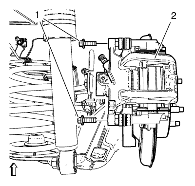
- Remove the 2 brake calliper pin bolts (1).
- Remove the brake caliper (2).
- Remove the brake calliper lower guide pin bolt (2).
- Without disconnecting the hydraulic brake flexible hose, pivot the calliper (1) upward and secure the calliper with heavy mechanics wire, or equivalent.
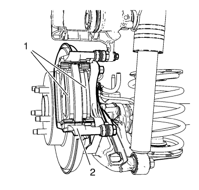
- Remove the brake pads (1) from the calliper mounting bracket (2).
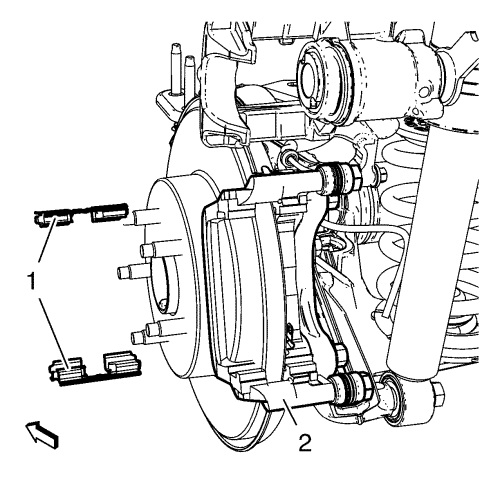
- Remove the brake pad retainer springs (1) from the calliper bracket (2).
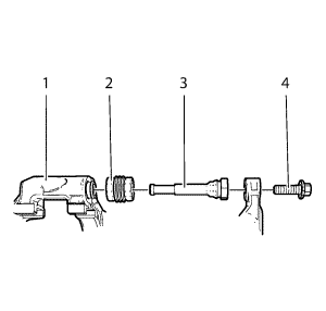
- Remove the brake calliper guide pins (3) from the brake calliper mounting bracket (1).
- Remove the brake calliper pin boots (2) from the brake calliper mounting bracket (1).
Installation Procedure
- Apply a thin coat of high temperature silicone lubricant to the brake calliper guide pin boots. Refer to Adhesives, Fluids, Lubricants, and Sealers for the recommended lubricant.
- Install the brake calliper pin boots (2) into the brake calliper mounting bracket (1). Do not hammer the calliper pin boots into the bracket. Ensure that the calliper pin boots are fully seated in the bracket.
- Apply a thin coat of high temperature silicone lubricant to the brake calliper guide pins.
- Install the brake calliper guide pins (3) to the brake calliper mounting bracket (1).
- Ensure the brake pad hardware mating surfaces are clean.
- Install the brake pad retainers (1) to the brake calliper bracket and apply a thin coat of high temperature silicone lubricant to the brake pad retainers. Refer to Adhesives, Fluids, Lubricants, and Sealers for the recommended lubricant.
Note: The wear sensor equipped disc brake pad must be mounted inboard of the rotor with the leading edge of the sensor facing the brake rotor during forward wheel rotation, or at the top of the pad when installed in vehicle position.
- Install the brake pads (1) to the calliper bracket (2).
- Install the brake calliper (2) to the brake calliper bracket.
Caution: Refer to Fastener Caution in the Preface section.
- Install the 2 brake calliper pin bolts (1) and tighten to 28 N·m (20 lb ft).
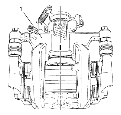
Note: Position of brake calliper piston cavity MUST be aligned horizontally to the embossed marking of brake calliper in order to prevent an appropriate installation.
- Checking position of piston cavity after assembling calliper (1).
- Install the tyre and wheel assembly. Refer to Tyre and Wheel Removal and Installation .
- Lower the vehicle.
- With the engine OFF, gradually apply the brake pedal approximately 2/3 of its travel distance.
- Slowly release the brake pedal.
- Wait 15 seconds, then gradually apply the brake pedal approximately 2/3 of its travel distance again until a firm brake pedal apply is obtained. This will properly seat the brake calliper pistons and brake pads.
- Fill the master cylinder auxiliary reservoir to the proper level. Refer to Master Cylinder Reservoir Filling .
| © Copyright Chevrolet. All rights reserved |
| © Copyright Chevrolet. All rights reserved |


