Orlando |
||||||||
|
|
|
|||||||
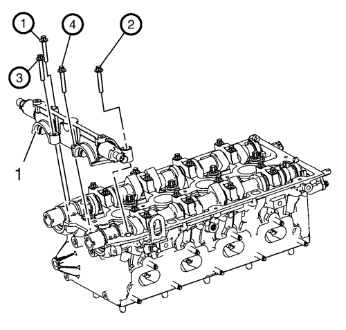
| • | EN-422 Installer |
| • | EN-6628-A Locking Tool |
For equivalent regional tools, refer to Special Tools .
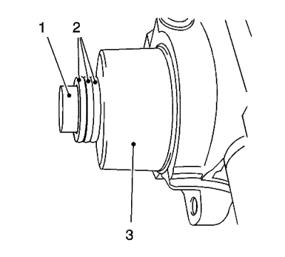
Counterhold at hexagon of camshaft.
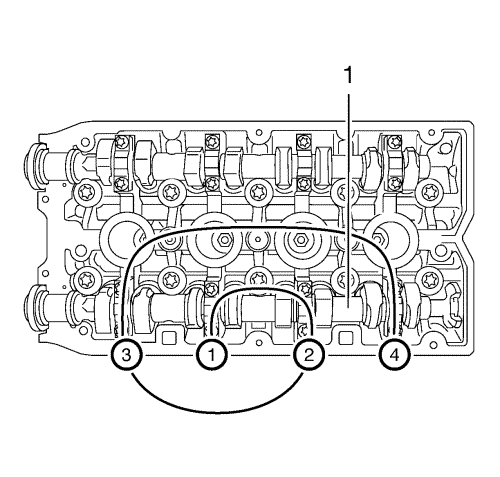
Note: Note removal sequence 1-4.
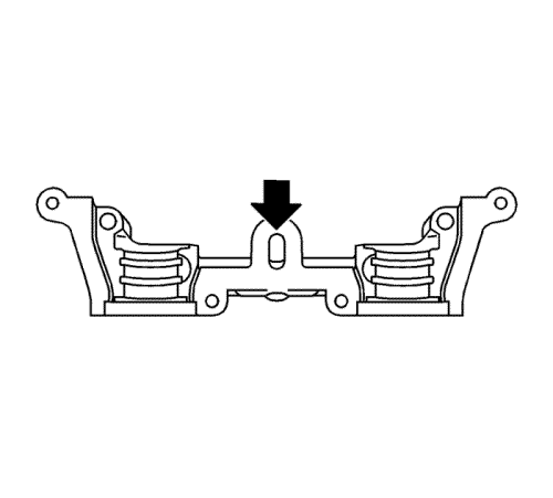
Note: Release the bearing support by striking it gently with a plastic hammer.
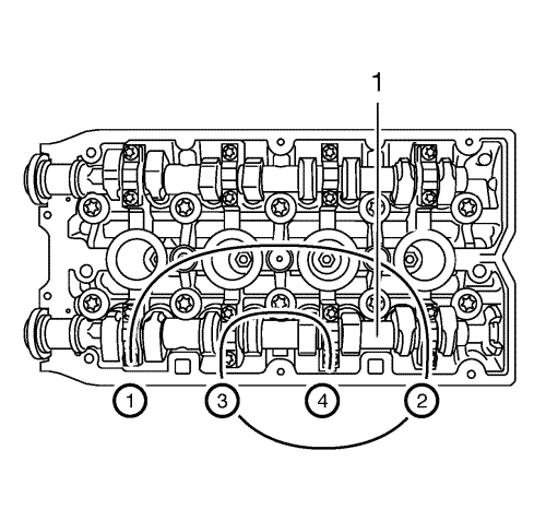
Note: Mark camshaft bearing caps before removal.
Note: Mark camshaft bearing caps before removal.
Note: Coat with MoS 2 lubricating paste.
Note: Note the identification marking on the camshaft bearing cover.
Caution: Refer to Fastener Caution in the Preface section.
Note: Coat with MoS 2 lubricating paste.
Note: Note the identification marking on the camshaft bearing cover.
Note: Sealing surfaces must be free from oil and grease.
Clean oil duct from any sealant residue.

Note: No sealant may reach the camshafts.
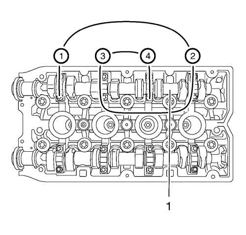
Note: Note installation sequence 1-4.
| 9.1. | First pass approximately to 2 N·m (18 lb in). |
| 9.2. | Second pass to 8 N·m (70 lb in). |
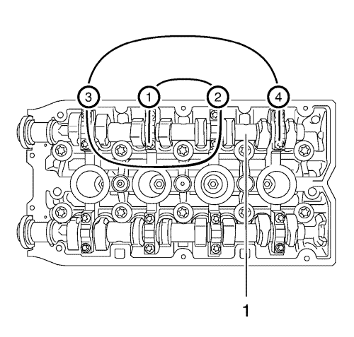
Note: Note removal sequence 1-4.
Note: It is necessary to remove the first camshaft bearing cap to apply the surface sealant.
Note: Release the bearing support by striking it gently with a plastic hammer.
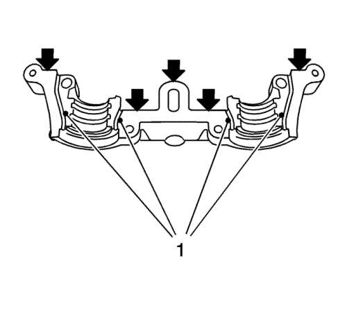
Note: Sealing surfaces must be free from oil and grease. It is essential to ensure that no sealant is applied outside the marked sealing areas. The grooves adjacent to the sealing surfaces must remain free from sealant.
Note: No sealant may reach the camshafts.
Note: Note the installation sequence 1-4.
| 15.1. | First pass approximately to 2 N·m (18 lb in). |
| 15.2. | Second pass to 8 N·m (70 lb in). |
| © Copyright Chevrolet. All rights reserved |
| © Copyright Chevrolet. All rights reserved |


