Brake Disc Assembled Lateral Runout Correction -- Indexing
Special Tools
CH-45101-100 Conical Brake Rotor Washers
For equivalent regional tools, refer to Special Tools .
Warning: Refer to Brake Dust Warning in the Preface section.
Note:
| • | Brake rotor thickness variation MUST be checked BEFORE checking for assembled lateral runout (LRO). Thickness variation exceeding the maximum acceptable level can cause brake pulsation. Refer to Brake Disc Thickness Measurement . |
| • | Brake rotor assembled LRO exceeding the maximum allowable specification can cause thickness variation to develop in the brake rotor over time, usually between 4,800 and 11,300 km (3,000 -- 7,000 mi). Refer to Brake Disc Assembled Lateral Runout Measurement . |
- Remove the CH 45101-100 washers and the lug nuts that were installed during the assembled LRO measurement procedure.
- Inspect the mating surface of the hub/axle flange and the brake rotor to ensure that there are no foreign particles or debris remaining.
- Index the brake rotor in a different orientation to the hub/axle flange.
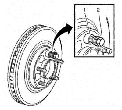
- Hold the rotor firmly in place against the hub/axle flange and install one of the CH 45101-100 washers (1) and one lug nut (2) onto the upper-most wheel stud.
- Continue to hold the rotor secure and tighten the wheel nut firmly by hand.
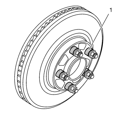
- Install the remaining CH-45101-100 washers (1) and lug nuts onto the wheel studs and tighten the nuts firmly by hand in a star-pattern.
- Tighten the lug nuts in a star-pattern to specification, in order to properly secure the rotor. Refer to Tyre and Wheel Removal and Installation .
- Measure the assembled LRO of the brake rotor. Refer to Brake Disc Assembled Lateral Runout Measurement .
- Compare the amount of change between this measurement and the original measurement.
- If this measurement is within specifications, proceed to step 14.
- If this measurement still exceeds specifications, repeat steps 1-9 until the best assembled LRO measurement is obtained.
- Matchmark the final location of the rotor to the wheel studs if the orientation is different than it was originally.
- If the brake rotor assembled LRO measurement still exceeds the maximum allowable specification, refer to Brake Disc Assembled Lateral Runout Correction .
- If the brake rotor assembled LRO is within specification, install the brake calliper and depress the brake pedal several times to secure the rotor in place before removing the CH-45101-100 washers and the lug nuts.
| © Copyright Chevrolet. All rights reserved |
| © Copyright Chevrolet. All rights reserved |


