Orlando |
||||||||
|
|
|
|||||||
| • | EN-958 Installer for 5 mm (0.2 in) Valve Stem Sealings |
| • | EN-6086 Basic Kit, Spring and Wedge Replacer |
| • | EN-6167 Counter Holder |
| • | EN-6215-3 Locking Pins |
For equivalent regional tools, refer to Special Tools .
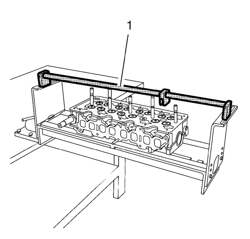
Note: Condition: All construction units are cleaned and checked. The cylinder head is installed on the assembly fixture and stands on the head.
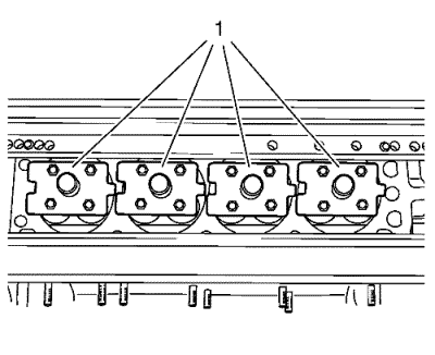
Note: Depending upon the combustion chamber organization, different holders must be used to protect the valves.
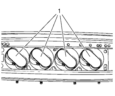
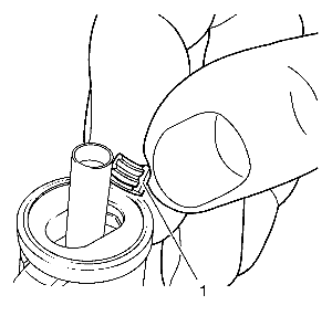
For 5 mm (0.2 in) use the EN-958 installer .
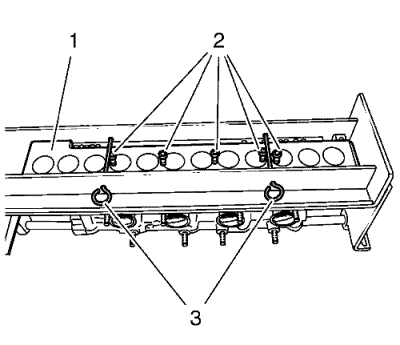
Note: It is necessary that the components of the assembly head are built together in correct sequence.
The respective sizes are hit on the head of the thrust pieces.
Note: The combinations of admission and thrust piece are to be kept compellingly, since otherwise the valve wedges can not be installed or the thrust pieces will damaged.
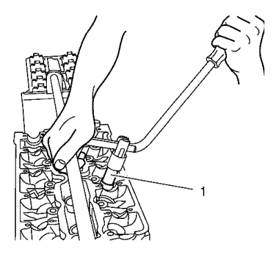
The combinations of admission and thrust piece are to be inferred from the overview.Attach assembly head to lever EN-6086 lever .
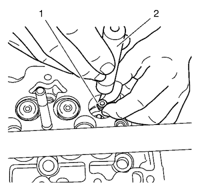
Note: To facilitate the assembly of the valve shim, the assembly head is to touch down (1) with the thrust piece on the valve stem. This avoids damage of the thrust pieces.
Press the assembly head with the lever tool carefully and slowly with little pressure until the valve wedges engage audibly into the valve stem.
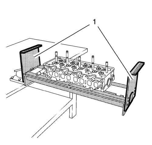
Note: After the assembly of all attachments the cylinder head is to be cleaned thoroughly.
Detach the cylinder head from the assembly fixture.
| © Copyright Chevrolet. All rights reserved |
| © Copyright Chevrolet. All rights reserved |


