Front Wheel Bearing and Hub Replacement
Special Tools
EN-45059 Torque Angle Sensor Kit
For equivalent regional tools, refer to Special Tools .
Removal Procedure
- Raise and support the vehicle. Refer to Lifting and Jacking the Vehicle .
- Remove the brake disc. Refer to Front Brake Disc Replacement .
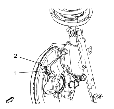
- Remove the wheel speed sensor screw (2).
- Remove the wheel speed sensor (1) from the steering knuckle.
- Remove the wheel drive shaft from the front wheel bearing/hub. Refer to Front Wheel Drive Shaft Replacement - Left Side and/or Front Wheel Drive Shaft Replacement - Right Side .
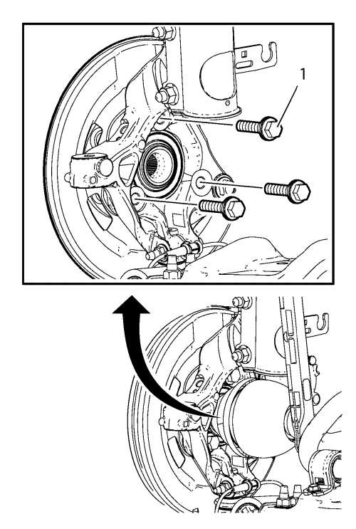
- Remove and DISCARD the front wheel bearing/hub bolts (1).
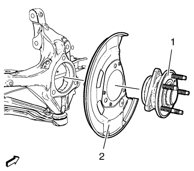
- Remove the front wheel bearing/hub (1) and front brake shield (2) from the steering knuckle.
Installation Procedure
- Position the front brake shield (2) and front wheel bearing/hub (1) assembly in the steering knuckle.
Warning: Refer to Torque-to-Yield Fastener Warning in the Preface section.
Caution: Refer to Fastener Caution in the Preface section.
- Install the NEW front wheel bearing/hub bolts (1).
- Tighten the bearing/hub bolts (1) in 3 passes. Use the EN-45059 angle meter.
| • | First pass to 90 N·m (66 lb ft) |
- Install the wheel drive shaft at the front wheel bearing/hub. Refer to Front Wheel Drive Shaft Replacement - Left Side or Front Wheel Drive Shaft Replacement - Right Side .
- Install the wheel speed sensor (1) to the steering knuckle.
- Install the wheel speed sensor screw (2) and tighten to 6 N·m (53 lb in).
- Install the brake disc. Refer to Front Brake Disc Replacement .
- Lower the vehicle.
| © Copyright Chevrolet. All rights reserved |
| © Copyright Chevrolet. All rights reserved |


