Engine/Transmission Mounting
Special Tools
| • | CH-49290 Mounting Engine/Gearbox |
| • | CH-49290-1 Ground Plate |
| • | CH-49290-4 Right Pin Bracket |
| • | CH-49290-5 Left Pin Bracket |
| • | CH-49290-7 Adapter Plate |
| • | CH-49290-8 Front Mounting Bracket Right |
| • | CH-49290-9 Front Mounting Bracket Left |
| • | CH-49290-10 Rear Mounting Bracket Right |
| • | CH-49290-11 Rear Mounting Bracket Left |
| • | CH-49290-12 Adapter Plate |
| • | CH-49290-14 Supporting Stand |
| • | CH-49290-15 Adapter Plate |
| • | CH-49290-16 Supporting Stand |
| • | CH-49290-18 Supporting Stand |
For equivalent regional tools, refer to Special Tools .
Prepare the CH-49290 for Mounting Engine
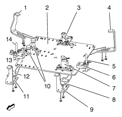
- Install the tool components at the CH-49290-1 plate (2).
| • | CH-49290-16 supporting with |
| | CH-49290-15 plate (3) at position 21 and V. |
| • | CH-49290-5 bracket (6) at position 02. |
| • | CH-49290-6 pin (5) at position E on the |
| • | CH-49290-14 supporting with |
| | CH-49290-12 plate (7) at position 13 and Q. |
| • | 2 bolts with 2 CH49290-18 supporting (10) at position 32 and position 40. |
| • | CH-49290-4 bracket (13) at position 01. |
| • | CH-49290-6 pin (14) at position B on the CH-49290-4 bracket (13). |
Note: Do not Install the CH-49290-10 bracket (1), CH-49290-11 bracket (4), CH-49290-7 plate (8), CH-49290-9 bracket (9), CH-49290-7 plate (12) and CH-49290-8 bracket (11) until the tool contacts the frame.
- Turn the CH49290-18 supporting (10), CH-49290-14 supporting (7) and CH-49290-16 supporting (3) downward.
Installation Procedure
- Raise the vehicle by its full height. Refer to Lifting and Jacking the Vehicle .
- Remove the front compartment insulator. Refer to Front Compartment Insulator Replacement .
- Install the CH-49290 mounting at the CH-904 frame .
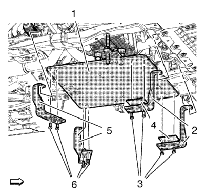
Note: Ensure that the 2 CH-49290-6 pins are fixed in both holes of the sub frame.
- Raise the CH-49290 mounting (1) with a jack.
- Install the CH-49290-9 bracket and CH-49290-8 bracket (2) with the 2 CH-49290-7 plate (4).
- Install the 4 bolts (3).
- Install the CH-49290-10 bracket and CH-49290-11 bracket (5).
- Install the 4 bolts (6).
- Lower the jack and remove it.
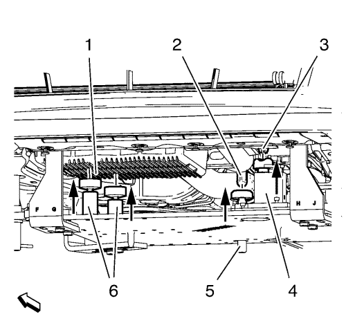
- Turn the CH-49290-14 supporting (4) upwards until it seats solidly at the front engine mount bracket (3).
- Turn the CH-49290-16 supporting (5) upwards until it seats solidly at the rear engine mount bracket (2).
- Turn the 2 CH49290-18 supporting (6) upwards until it seats solidly at the oil pan (1).
- Remove the CH-904 frame from the CH-49290 mounting .
Removal Procedure
- Install the CH-904 frame to the CH-49290 mounting .
- Support the CH-49290 mounting (1) with a jack.
- Remove the 4 bolts (3).
- Remove the CH-49290-9 bracket and CH-49290-8 bracket (2) with the 2 CH-49290-7 plate (4).
- Remove the 4 bolts (6).
- Remove the CH-49290-10 bracket and CH-49290-11 bracket (5).
- Lower the CH-49290 mounting with a jack.
| © Copyright Chevrolet. All rights reserved |
| © Copyright Chevrolet. All rights reserved |


