Transmission Replacement
Special Tools
| • | CH-49290 Engine Support Tool |
| • | DT-47648 Transmission Holder |
| • | EN-47649 Engine Support Fixture |
For equivalent regional tools, refer to Special Tools .
Removal Procedure
- Remove battery tray. Refer to Battery Tray Replacement .
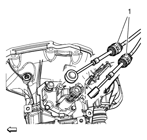
- Disconnect the gear lever and selector lever cables (1) from the shift control lever and the selector and gear lever cable bracket.
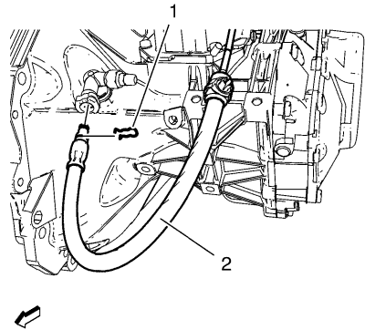
Note: Before disconnecting the clutch actuator cylinder front pipe, remove the clutch/brake fluid from the reservoir tank.
- Remove the clutch actuator cylinder front pipe retainer (1).
Disconnect the clutch actuator cylinder front pipe (2) from the clutch actuator cylinder pipe elbow.
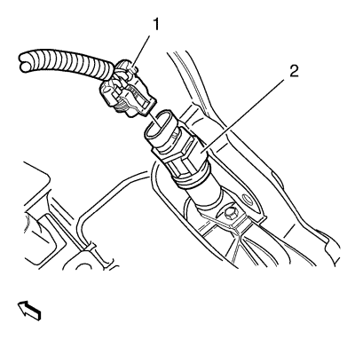
- Disconnect the electrical connector (1) from the speedometer driven gear (2).
- Disconnect the electrical connector from the reverse lamp switch.
- Disconnect the wiring harness clamp from the transmission.
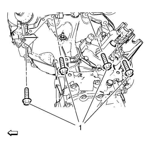
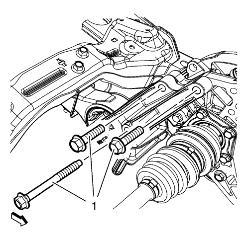
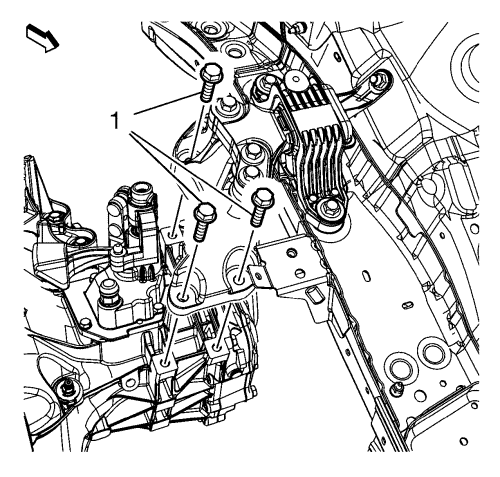
- Remove the upper transmission bolts (1).
- Install the EN-47649 support fixture. Refer to Engine Support Fixture .
- Raise and support the vehicle. Refer to Lifting and Jacking the Vehicle .
Note: The SPX installation manual is supplied with the special tool and is also available online from SPX directly. Go to www.spxtools-shop.com.
- Assemble the CH-49290 support tool (1) according to the details provided in the SPX installation manual.
- Support the CH-904 base frame on a jack.
- Support the CH-49290 support tool on the CH-904 base frame.
Note: The SPX installation manual is supplied with the special tool and is also available online from SPX directly. Go to www.spxtools-shop.com.
- Install the CH-49290 support tool (1) according to the details provided in the SPX installation manual.
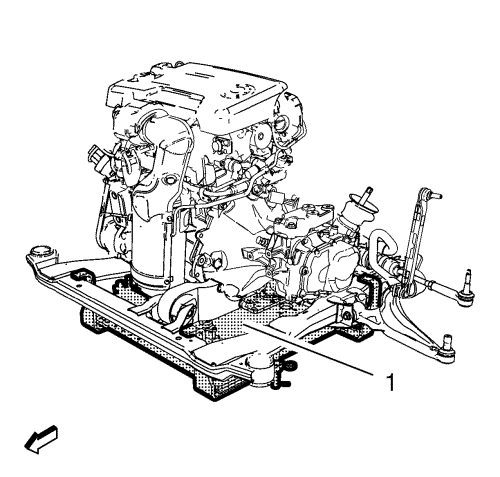
- Remove the drivetrain and front suspension frame. Refer to Drivetrain and Front Suspension Frame Replacement .
- Disconnect the left front wheel drive shaft from the transmission. Refer to Front Wheel Drive Shaft Replacement - Left Side .
- Disconnect the right front wheel drive shaft from the transmission. Refer to Front Wheel Drive Shaft Replacement - Right Side .
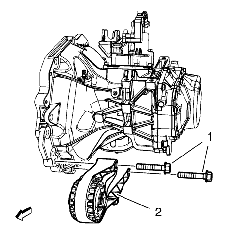
- Remove the transmission front mount bolts (1) and the transmission front mount (2).
- Remove the transmission mount bracket bolts (1) and the transmission mount bracket - rear.
- Remove the starter. Refer to
Starter Replacement : 2.0L Diesel LNP with MT → 2.0L Diesel LNP with AT → 1.6L LDE, LXV, 1.8L 2H0, LUW and LFH .
- Lower the vehicle.
- Remove the transmission mount bolts (1).
- Lower the engine and the transmission on the left hand side with the EN-47649 support fixture.
- Raise the vehicle.
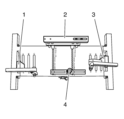
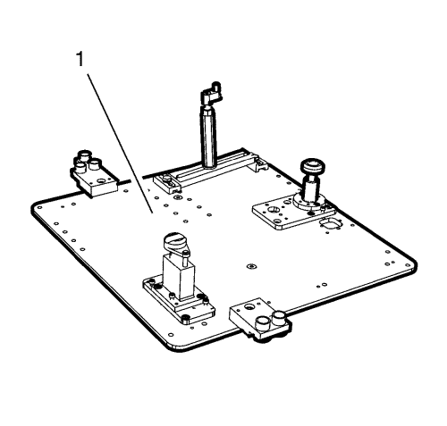
- Place DT-47648 holder on CH-904 frame and preinstall the supports as shown in the illustration.
- Preinstall DT-47648-2 clutch housing support (4) to position 3 on the base plate.
- Preinstall DT-47648-4 transmission housing support (2) to position 4 on the base plate.
- Preinstall DT-47648-5 left support (1) to position A on the base plate.
- Preinstall DT-47648-5 right support (3) to position F on the base plate.
Note: Before placing in position, slacken all bolt connections of the swivel arms and supports as far as the base plate. Adjust the supports for the converter housing and transmission housing using the spindles until they are as low as possible.
- Attach the DT-47648 holder to the transmission.
- Align DT-47648 holder under transmission.
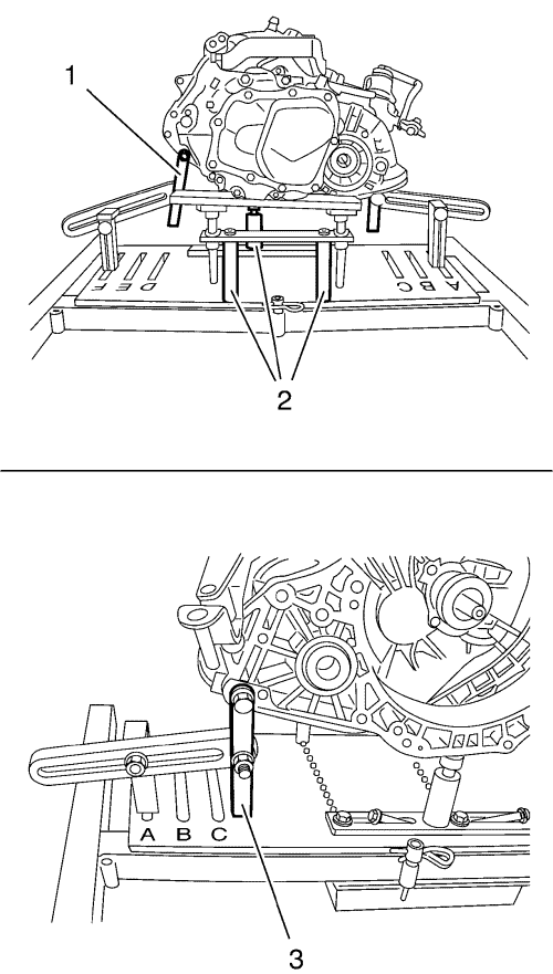
- Attach swivel arms (1, 3) to transmission.
Note: Align the swivel arms so that as little leverage as possible is created.
- Tighten the bolt connections of the swivel arms, starting from the transmission and going as far as the base plate.
- Position supports for clutch housing and transmission housing on transmission by twist up the spindles (2).
- Tighten bolt connections of the supports.
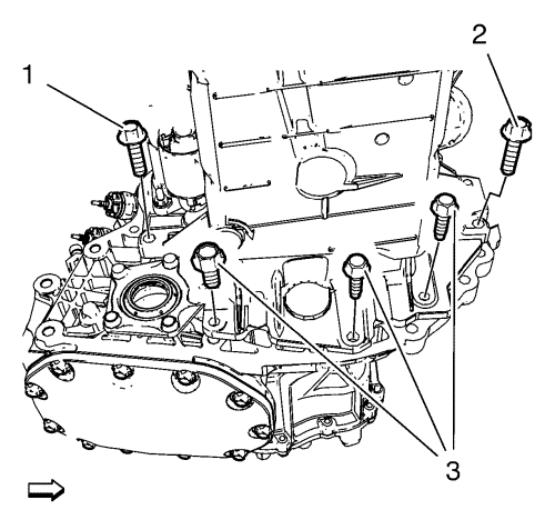
- Remove the transmission bolts (1, 2, 3).
- Separate the transmission from the engine.
- Lower the transmission with the transmission jack and DT-47648 holder far enough to remove the transmission.
Installation Procedure
- Raise the transmission with the transmission jack and DT-47648 holder and position the transmission to the engine.
Caution: Refer to Fastener Caution in the Preface section.
- Install the transmission bolts (1, 2) and tighten to 75 N·m (55 lb ft).
Install the transmission bolts (3) and tighten to 45 N·m (33 lb ft).
- Remove the transmission jack with the DT-47648 holder.
- Lower the vehicle.
- Raise the engine and the transmission on the left hand side with the EN-47649 support fixture.
- Install the transmission mount bolts (1) but do not tighten yet.
- Raise the vehicle.
- Install the starter. Refer to
Starter Replacement : 2.0L Diesel LNP with MT → 2.0L Diesel LNP with AT → 1.6L LDE, LXV, 1.8L 2H0, LUW and LFH .
- Install the transmission mount bracket - rear and tighten the bolts (1) to 100 N·m (74 lb ft).
- Install the transmission front mount (2) and tighten the bolts (1) to 100 N·m (74 lb ft).
- Connect the left front wheel drive shaft to the transmission. Refer to Front Wheel Drive Shaft Replacement - Left Side .
- Connect the right front wheel drive shaft to the transmission. Refer to Front Wheel Drive Shaft Replacement - Right Side .
- Install the drivetrain and front suspension frame. Refer to Drivetrain and Front Suspension Frame Replacement .
- Lower the vehicle.
- Remove the EN-47649 support fixture. Refer to Engine Support Fixture .
- Tighten the transmission mount bolts (1) to 62 N·m (46 lb ft).
- Raise the vehicle.
- Lower the CH-49290 support tool (1) with the CH-904 base frame and a jack.
- Remove the CH-49290 support tool from the CH-904 base frame.
Note: The SPX installation manual is supplied with the special tool and is also available online from SPX directly. Go to www.spxtools-shop.com.
- Disassemble the CH-49290 support tool (1) according to the details provided in the SPX installation manual.
- Install the upper transmission bolts (1) and tighten to 75 N·m (55 lb ft).
- Connect the electrical connector (1) to the speedometer driven gear (2).
- Connect the electrical connector to the reverse lamp switch.
- Connect the wiring harness clamp to the transmission.
Note: Clutch actuator cylinder front pipe must engage noticeably.
- Connect the clutch actuator cylinder front pipe (2) to the clutch actuator cylinder pipe elbow.
- Lock the clutch actuator cylinder front pipe retainer (1).
- Connect the gear lever and selector lever cables (1) to the shift control lever and to the selector and shift lever cable bracket.
- Adjust the gear lever and selector lever cables. Refer to Manual Gearbox Gear Lever and Selector Lever Cable Adjustment .
- Bleed the clutch hydraulic system. Refer to Hydraulic Clutch System Bleeding .
- Inspect the transmission fluid level. Refer to Transmission Fluid Level Inspection .
- Install the battery tray. Refer to Battery Tray Replacement .
- Road test the vehicle.
| © Copyright Chevrolet. All rights reserved |
| © Copyright Chevrolet. All rights reserved |


