Rear Brake Rotor Replacement
Special Tools
| • | CH-41013 Rotor Resurfacing Kit |
| • | CH-42450-A Wheel Hub Resurfacing Kit |
For equivalent regional tools, refer to Special Tools .
Removal Procedure
Warning: Refer to Brake Dust Warning in the Preface section.
Caution: Support the brake calliper with heavy mechanic wire, or equivalent, whenever it is separated from its mount and the hydraulic flexible brake hose is still connected. Failure to support the calliper in this manner will cause the flexible brake hose to bear the weight of the calliper, which may cause damage to the brake hose and in turn may cause a brake fluid leak.
- Remove the brake calliper and the calliper mounting bracket as an assembly from the steering knuckle. Refer to Rear Brake Calliper Bracket Replacement .
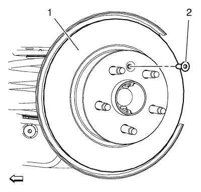
- Matchmark the position of the brake rotor to the wheel studs.
- Remove the rear brake rotor bolt (2).
- Remove rear brake rotor (1) from the wheel hub.
Installation Procedure
- Using the CH-42450-A kit , thoroughly clean any rust or corrosion from the mating surface of the hub/axle flange.
- Using the CH-41013 kit , thoroughly clean any rust or corrosion from the mating surface and mounting surface of the brake rotor.
- Inspect the mating surfaces of the hub/axle flange and the rotor to ensure that there are no foreign particles or debris remaining.
- Install the brake rotor (1) to the hub/axle flange. Use the matchmark made prior to removal for proper orientation to the flange.
Caution: Refer to Fastener Caution in the Preface section.
- Install rear brake rotor bolt (2) and tighten to 9 N·m (80 lb in).
- Install the brake calliper and the calliper mounting bracket assembly to the steering knuckle. Refer to Rear Brake Calliper Bracket Replacement .
- If the brake rotor was removed and installed as part of a brake system repair, measure the assembled LRO of the brake rotor to ensure optimum performance of the disc brakes. Refer to Brake Disc Assembled Lateral Runout Measurement .
- If the brake rotor assembled LRO measurement exceeds the specification, bring the LRO to within specifications. Refer to Brake Disc Assembled Lateral Runout Correction .
| © Copyright Chevrolet. All rights reserved |
| © Copyright Chevrolet. All rights reserved |


