Orlando |
||||||||
|
|
|
|||||||
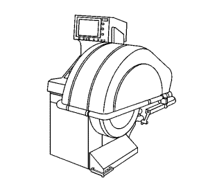
Warning: Failure to adhere to the following precautions before tyre balancing can result in personal injury or damage to components: • Clean away any dirt or deposits from the inside of the wheels. • Remove any stones from the tread. • Wear eye protection. • Use coated weights on aluminium wheels.
Tyre and wheel balancers can drift out of calibration over time, or can become inaccurate as a result of heavy use. There will likely not be any visual evidence that a calibration problem exists. If a balancer is not calibrated within specifications, and a tyre and wheel assembly is balanced on that machine, the assembly may actually be imbalanced.
Tyre and wheel assembly balancer calibration should be checked approximately every 2 weeks, if the machine is used frequently, and/or whenever the balance readings are questionable.
Note: If the balancer fails any of the steps in this calibration test, the balancer should be calibrated according to the manufacturer's instructions. If the balancer cannot be calibrated, contact the manufacturer for assistance.
Inspect the calibration of the tyre and wheel assembly balancer according to the manufacturer's recommendations, or perform the following test.
Specification
Zero within 7 g (¼ oz)
| • | In the static and dynamic modes, the balancer should call for 85 g (3 oz) of weight, 180 degrees opposite the test weight. |
| • | In the dynamic mode, the weight should be called for on the flange of the wheel opposite the test weight. |
Specification
Maximum variation: 7 g (¼ oz)
Specification
Maximum variation: 7 g (¼ oz)
There are 2 types of tyre and wheel balance:
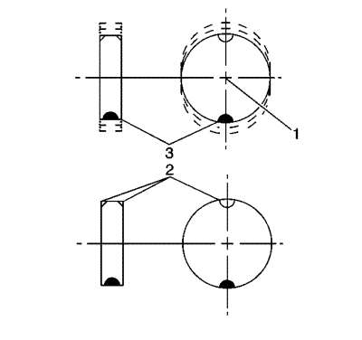
Static balance is the equal distribution of weight around the wheel circumference. The wheel balance weights (2) are positioned on the wheel in order to offset the effects of a heavy spot (3). Wheels that have static imbalance can produce a bouncing action called tramp.
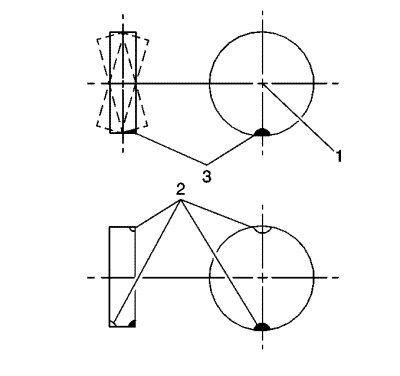
Dynamic balance is the equal distribution of weight on each side of the tyre and wheel assembly centreline. The wheel balance weights (2) are positioned on the wheel in order to offset the effects of a heavy spot (3). Wheels that have dynamic imbalance have a tendency to move from side to side and can cause an action called shimmy.
Most off-vehicle balancers are capable of checking both types of balance simultaneously.
As a general rule, most vehicles are more sensitive to static imbalance than to dynamic imbalance; however, vehicles equipped with low profile, wide tread path, high performance tyres and wheels are susceptible to small amounts of dynamic imbalance. As little as 14-21 g (½-¾ oz) imbalance is capable of inducing a vibration in some vehicle models.
Note: When balancing tyre and wheel assemblies, use a known good, recently calibrated, off-vehicle, two-plane dynamic balancer set to the finest balance mode available.
Regard aftermarket wheels, especially those incorporating universal lug patterns, as potential sources of runout and mounting concerns.
Tyre and wheel assemblies can be balanced using either the static or dynamic method.

Note: When balancing factory aluminium wheels with clip-on wheel balance weights, be sure to use special polyester-coated weights. These coated weights reduce the potential for corrosion and damage to aluminium wheels.
These coated weights reduce the potential for corrosion and damage to aluminium wheels.
| • | MC (1) and AW (2) series weights are approved for use on aluminium wheels. |
| • | P (3) series weights are approved for use on steel wheels only. |
| • | T (4) series coated weights are approved for use on both steel and aluminium wheels. |
Note: Use a nylon or plastic-tipped hammer when installing coated clip-on wheel balance weights to minimize the possibility of damage to the polyester coating.
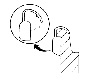
The contour and style of the wheel rim flange will determine which type of clip-on wheel weight (1) should be used. The weight should follow the contour of the rim flange. The weight clip should firmly grip the rim flange.
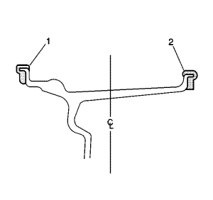
When static balancing, locate the wheel balance weights on the inboard flange (2) if only 28 g (1 oz) or less is called for. If more than 28 g (1 oz) is called for, split the weights as equally as possible between the inboard (2) and outboard (1) flanges.
When dynamic balancing, locate the wheel balance weights on the inboard (2) and outboard (1) rim flanges at the positions specified by the wheel balancer.
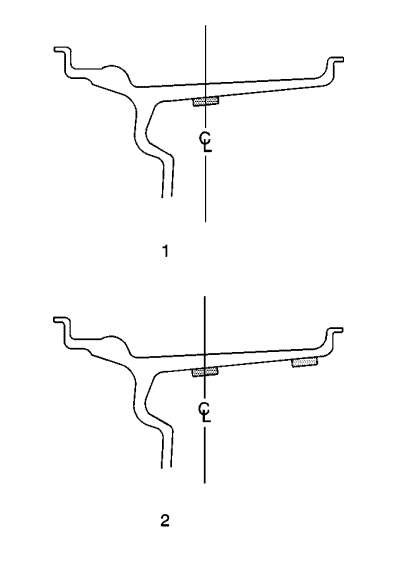
Note: When installing adhesive balance weights on flangeless wheels, do NOT install the weight on the outboard surface of the rim.
Adhesive wheel balance weights may be used on factory aluminium wheels. Perform the following procedure to install adhesive wheel balance weights.
| • | When static balancing, locate the wheel balance weights along the wheel centreline (1) on the inner wheel surface if only 28 g (1 oz) or less is called for. If more than 28 g (1 oz) is called for, split the weights as equally as possible between the wheel centreline and the inboard edge of the inner wheel surface (2). |
| • | When dynamic balancing, locate the wheel balance weights along the wheel centreline and the inboard edge of the inner wheel surface (2) at the positions specified by the wheel balancer. |
Note: Do not use abrasives to clean any surface of the wheel.
| © Copyright Chevrolet. All rights reserved |
| © Copyright Chevrolet. All rights reserved |


