Front Wheel Drive Shaft Replacement - Right Side
Special Tools
| • | CH-6003 Axle Shaft Remover |
| • | CH-49376 Holding Spanner |
| • | CH-49400 Hub Spindle Remover |
For equivalent regional tools, refer to Special Tools .
Removal Procedure
Warning: To prevent personal injury and/or component damage, do not allow the weight of the vehicle to load the front wheels, or attempt to operate the vehicle, when the wheel drive shaft(s) or wheel drive shaft nut(s) are removed. To do so may cause the inner bearing race to separate, resulting in damage to brake and suspension components and loss of vehicle control.
Caution: Wheel drive shaft boots, seals and clamps should be protected from sharp objects any time service is performed on or near the wheel drive shaft(s). Damage to the boot(s), the seal(s) or the clamp(s) may cause lubricant to leak from the joint and lead to increased noise and possible failure of the wheel drive shaft.
- Raise and suitably support the vehicle. Refer to Lifting and Jacking the Vehicle .
- Remove the tire and wheel assembly. Refer to Tyre and Wheel Removal and Installation .
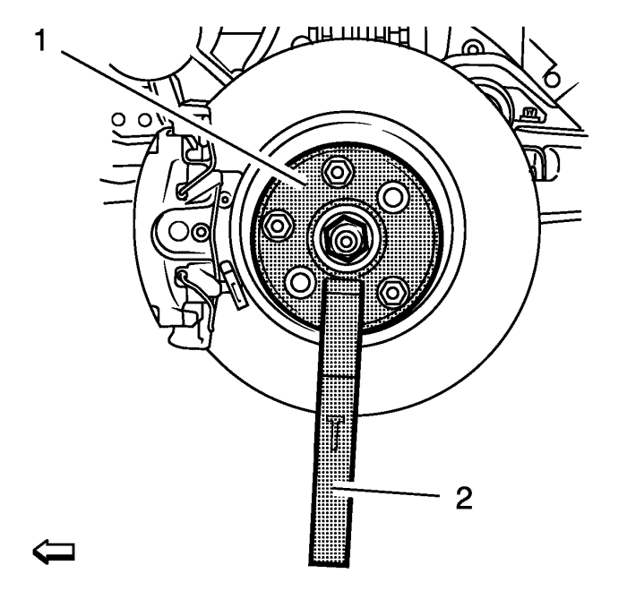
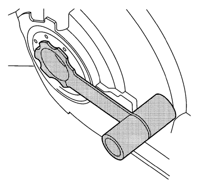
- Using the CH-49376 holding wrench (1) with EN-956-1 extension (2).
Note: DO NOT re-use the wheel drive shaft nut. DISCARD the nut and replace with NEW.
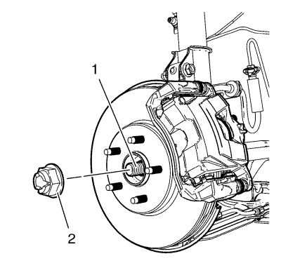
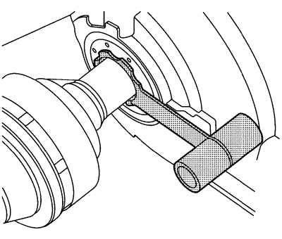
- Remove and DISCARD the wheel drive shaft nut (2) from the wheel drive shaft (1).
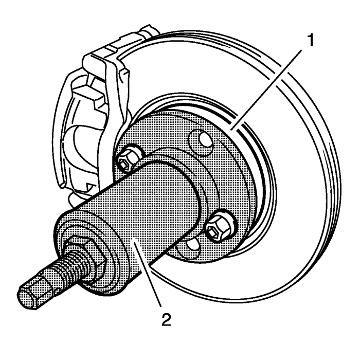
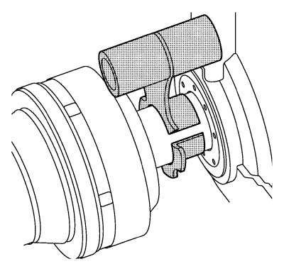
- Using the CH-49400 remover (2), separate the brake rotor and wheel bearing/hub assembly (1).
- Remove the outer tie rod assembly from the steering knuckle. Refer to Steering Linkage Outer Track rod Replacement .
- Remove the ball joint from the steering knuckle. Refer to Lower Control Arm Replacement .
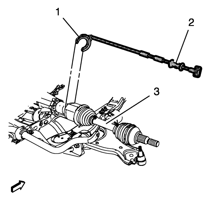
- Using the CH-313 slide hammer (2) with CH-6003 remover (1) remove the wheel drive shaft (3) from the vehicle.
Installation Procedure
Note: DT-6332 protector not needed for vehicles with intermediate shaft.
- Install the DT-6332 protector into the differential output shaft seal.
Note: In order to prevent lubricant leaks, use care when installing the wheel drive shaft to the differential. Do not damage the oil seal. Replace the oil seal if it becomes nicked, distorted, or otherwise damaged.
Note: DT-6332 protector not needed for vehicles with intermediate shaft.
- Carefully install the wheel drive shaft into the differential until the splines are past the DT-6332 protector.
Note: DT-6332 protector not needed for vehicles with intermediate shaft.
- Remove the DT-6332 protector from the differential output shaft seal.
- Installing the wheel drive shaft into the differential until the retaining ring is fully seated.
- Confirm that the front wheel drive shaft retaining ring is properly seated by holding the inner housing and pull the inner housing outwards and inwards. The wheel drive shaft is proper installed, if it can be pulled about 1 to 2 mm (0.04 to 0.08 in).
- Install the front wheel drive shaft into the front wheel bearing/hub.
- Install the ball joint to the steering knuckle. Refer to Lower Control Arm Replacement .
- Install the outer tie rod assembly at the steering knuckle. Refer to Steering Linkage Outer Track rod Replacement .
- Install the NEW wheel drive shaft nut (2) on the wheel drive shaft (1) in 3 passes.
Caution: Refer to Fastener Caution in the Preface section.
Caution: Refer to Torque-to-Yield Fastener Caution in the Preface section.
- Use the CH-49376 holding wrench (1) with EN-956-1 extension (2) to counterhold while tightening the wheel drive shaft nut.
| • | Tighten the wheel drive shaft nut a first pass to 150 N·m (111 lb ft). |
| • | Release the wheel drive shaft nut in a second pass trough 45 degrees. |
| • | Retighten the wheel drive shaft nut a final pass to an additional 250 N·m (184 lb ft). |
- Install the tire and wheel assembly. Refer to Tyre and Wheel Removal and Installation .
- Lower the vehicle.
- Inspect the transaxle fluid level. Refer to Transmission Fluid Level and Condition Check .
| © Copyright Chevrolet. All rights reserved |
| © Copyright Chevrolet. All rights reserved |


