Drivetrain and Front Suspension Frame Replacement
Special Tools
| • | CH 49289 Centring Adapter |
For equivalent regional tools, refer to Special Tools .
Removal Procedure
- Support the radiator and condenser from above using the condenser tabs on each side.
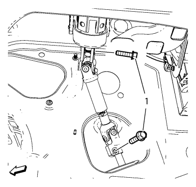
- Remove the lower steering intermediate shaft bolt (1).
- Raise the vehicle on a hoist. Refer to Lifting and Jacking the Vehicle .
- Remove the tyre and wheel assemblies. Refer to Tyre and Wheel Removal and Installation .
- Remove the exhaust front pipe. Refer to
Exhaust Front Pipe Replacement : 2.0L Diesel LNP → LDE, LLU, LXT, LXV, L2W, 2H0, LFH,LGE .
- Remove the front compartment splash shield. Refer to Front Compartment Splash Shield Replacement .
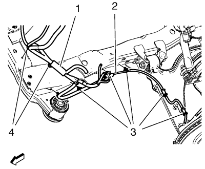
- Remove the wheel speed sensor wiring harness (2) from the frame on both sides.
Remove the wiring harness retainers (3) from the frame and the lower control arm.
- Remove the radiator wiring harness (1) from the frame.
Remove the wiring harness retainers (4) from the frame.
- Remove the lower ball joints from the steering knuckles. Refer to Lower Control Arm Replacement .

- Remove the stabiliser link nut (1) from the strut.
- Remove the outer track rods and track rod nuts from the steering knuckles. Refer to Steering Linkage Outer Track rod Replacement .
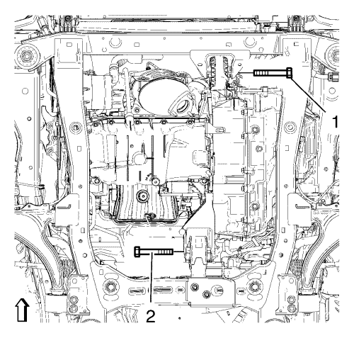
- Remove the front (1) and the rear (2) transmission mount bracket bolts.
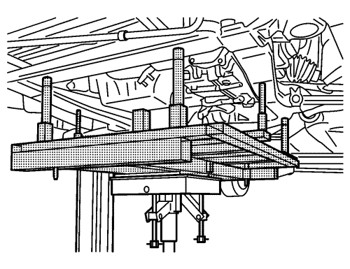
- Raise the CH 904 frame and CH 49289 adapter with the hydraulic jack until it contacts the frame.
- Turn the front wheels to the straight forward position and secure the steering wheel from moving.
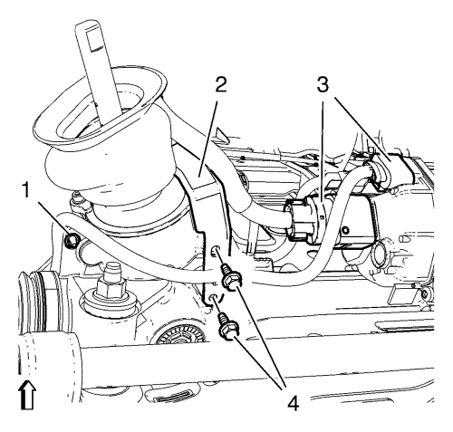
- Carefully disconnect 2 wiring harness plugs (3) from the steering gear with a suitable tool. Use the following procedure to disconnect the 2 wiring harness plugs:
| 15.1. | Insert a small flat bladed tool into the pocket of the connector retention feature. |
| 15.2. | Gently move the retention feature back and pull on the connector to disconnect the connector. |
Note : Positioning pins (2, 3) of CH 49289 adapter MUST stick into holes of drive train frame.
- Check if wheel alignment is required.
Move out position pins (1) and try to insert into underbody holes.
If guide pins can NOT be inserted, the Wheel Alignment Measurement is required after installation of the drive train frame.
- Loosen the front bumper energy absorber bracket bolt.
- Secure the power steering gear to the vehicle.
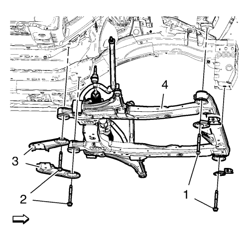
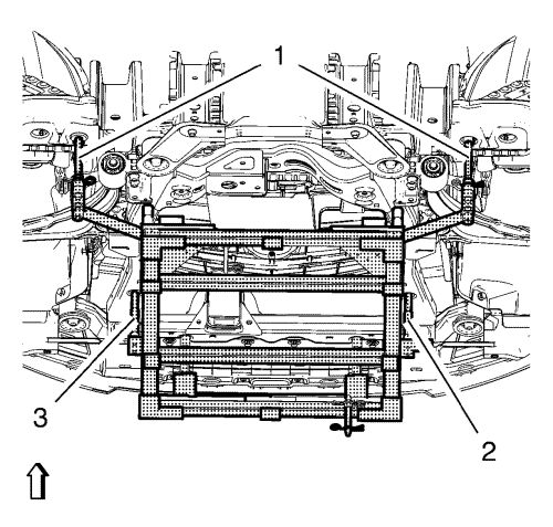
- Remove the frame front bolts (1).
- Remove the frame rear bolts (2).
- Remove the frame reinforcements (3).
- Remove the frame (4) from the vehicle.
- Remove the following components if replacing the frame:
| • | The radiator support brackets. |
Installation Procedure
- Install the following components on the drivetrain and front suspension frame if removed:
| • | The radiator support brackets. |
Note : Positioning pins (1) of CH 49289 adapter MUST be extended in order to guide into underbody holes.
- Extend positioning pins (1) of CH 49289 adapter prior raising the suspension frame.
- Raise the frame (4) carefully, using CH 49289 adapter.
- Install the frame reinforcements (3).
Caution : Refer to Fastener Caution in the Preface section.
- Install the frame rear bolts (2) and tighten to 160 N·m (118 lb ft).
- Install the frame front bolts (1) and tighten to 160 N·m (118 lb ft).
- Remove the support of the power steering gear.
- Install and tighten 2 wiring harness bracket bolts (4) to 9 N·m (80 lb in).
- Tighten wiring harness retainer (1) to steering gear.
- Connect 2 wiring harness plugs (3).
- Install the front bumper energy absorber bracket bolt.
- Install the front transmission mount bolt (1) and tighten to 100 N·m (74 lb ft).
- Install the rear transmission mount bracket bolt (2) and tighten to 100 N·m (74 lb ft).
- Install the outer track rods and track rod nuts to the steering knuckles. Refer to Steering Linkage Outer Track rod Replacement .
- Install the steering linkage track rod. Tighten the steering linkage tie rod nut (1) to 35 N·m (26 lb ft).
- Install the lower ball joints to the steering knuckles. Refer to Lower Control Arm Replacement .
- Install the wheel speed sensor wiring harness (2) to the frame on both sides.
Install the wiring harness retainers (3) to the frame and the lower control arm.
- Install the radiator wiring harness (1) to the frame.
Install the wiring harness retainers (4) to the frame.
- Install the lower steering intermediate shaft (1) bolt and tighten to 34 N·m (25 lb ft).
- Remove the support of the radiator and condenser.
- Lower the vehicle on a hoist. Refer to Lifting and Jacking the Vehicle .
- Install the tyre and wheel assemblies. Refer to Tyre and Wheel Removal and Installation .
- Install the exhaust front pipe. Refer to
Exhaust Front Pipe Replacement : 2.0L Diesel LNP → LDE, LLU, LXT, LXV, L2W, 2H0, LFH,LGE .
- If replacing the frame, check wheel alignment. Refer to Wheel Alignment Measurement .
| © Copyright Chevrolet. All rights reserved |
| © Copyright Chevrolet. All rights reserved |


