Headlamp Mount Panel Replacement - Welding
Note : According to different corrosion warranties, only the regional mandatory joining methods are allowed.
Removal Procedure
Warning : Refer to Approved Equipment for Collision Repair Warning in the Preface section.
Warning : Refer to Glass and Sheet Metal Handling Warning in the Preface section.
- Disable the SIR System. Refer to SIR Disabling and Enabling .
- Disconnect the battery negative cable. Refer to
Battery Negative Cable Disconnection and Connection : without Start/Stop System .
- Remove all related panels and components.
- Visually inspect the damage. Repair as much of the damage as possible.
- Remove the sealers and anti-corrosion materials from the repair area, as necessary. Refer to
Anti-Corrosion Treatment and Repair : Base .
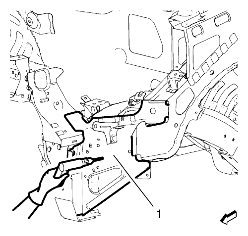
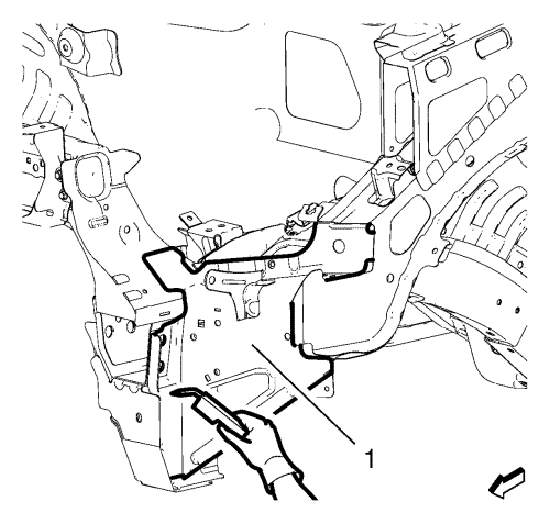
- Locate and mark all the necessary factory welds of the headlamp mount panel (1).
- Drill all factory welds. Note the number and location of welds for installation of the service assembly.
- Cut the adhesive (1) with an appropriate tool.
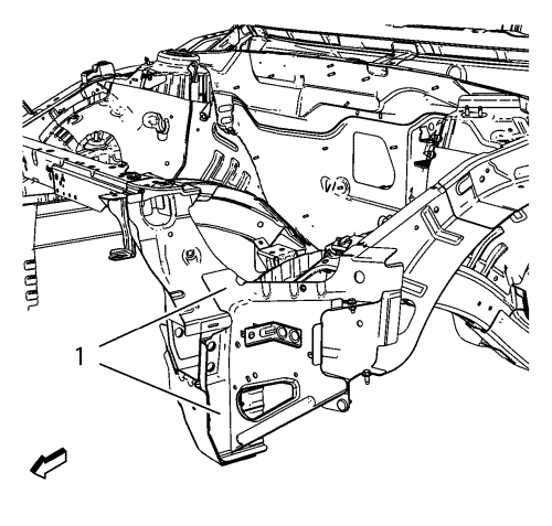
- Remove the headlamp mount panel (1).
Installation Procedure
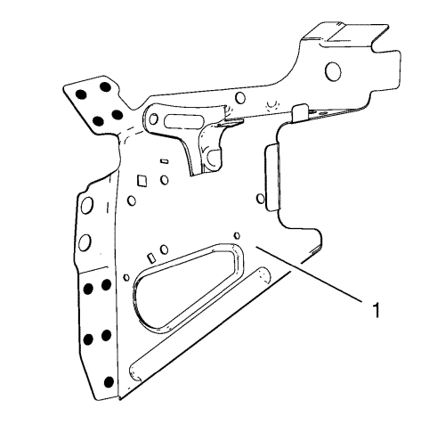
- Drill 8 mm (5/16 in) for plug welding instead of the adhesive noted from the original panel.
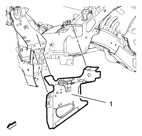
- Drill 8 mm (5/16 in) for plug welding along the edges of the headlamp mount panel (1) where the spotwelder cannot be applied.
- Clean and prepare the attaching surfaces for welding.
- Position the headlamp mount panel (1) on the vehicle.
- Verify the fit of the headlamp mount panel.
- Clamp the headlamp mount panel into position.
- Plug weld the headlight mount panel (1) accordingly.
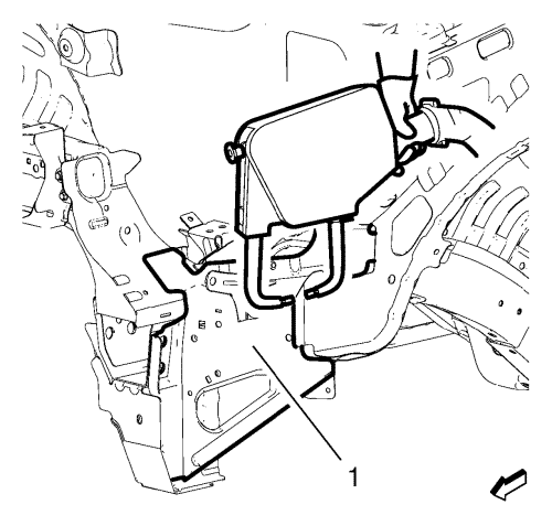
- Spot weld the headlight mount panel (1) accordingly.
- Apply the sealers and anti-corrosion materials to the repair area, as necessary. Refer to
Anti-Corrosion Treatment and Repair : Base .
- Paint the repaired area.
- Install all related panels and components.
- Connect the battery negative cable. Refer to
Battery Negative Cable Disconnection and Connection : without Start/Stop System .
- Enable the SIR system. Refer to SIR Disabling and Enabling .
| © Copyright Chevrolet. All rights reserved |
| © Copyright Chevrolet. All rights reserved |


