- Position the vehicle on level ground and move the front wheels to the straight-ahead position.
- Disconnect the battery negative connection. Refer to
Battery Negative Cable Disconnection and Connection : without Start/Stop System
- Remove the air inlet grille panel. Refer to Air Inlet Grille Panel Replacement .
- Remove the inside rearview mirror. Refer to Inside Rearview Mirror Replacement .
- Remove the remote control door lock receiver. Refer to Remote Control Door Lock Receiver Replacement .
- Remove the windscreen outside moisture sensor. Refer to Windscreen Outside Moisture Sensor Replacement .
- Use BO-46974 removal system .
Warning: Refer to Defroster Outlet Warning in the Preface section.
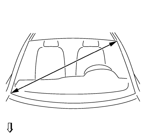
- Take the diagonal measurement (1) of the windscreen.
- Cut cutting wire into four times lengths.
Approx. 6400 mm (251.9677 in), the circumference of the corresponding roll of wire is about 1000 mm (39.369 in).
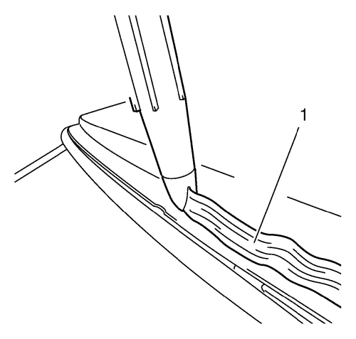
- Heat the awl with a suitable tool.
Note: Ensure that the windscreen is not damaged in the process, otherwise stress cracks in the windscreen may occur.
- Stick the awl (1) with adhesive bed in the area of the front wall.
- Pull the wire through.
| • | Thread the cutting wire into the hole of the awl and bend it over. |
| • | Pull the cutting wire with the awl to the middle of the steering wheel in the interior. |
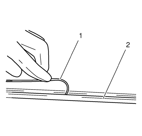
Note: The cutting wire (1) should be rolled in beneath the rubber window seal (2) at the windscreen.
- Lay the wire under the windscreen all the way round.
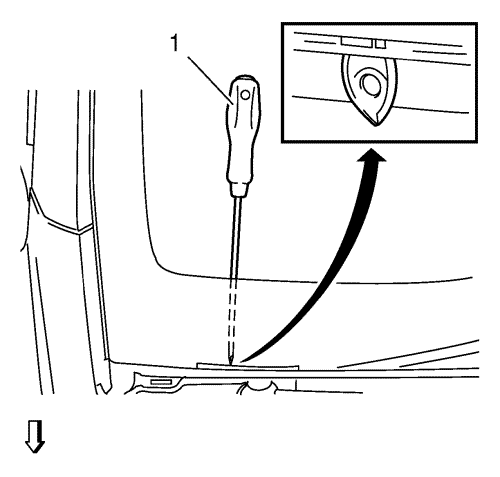
- Pull the second wire end through.
| • | Stick awl approx. 1 cm (0.393 in) overlapping the first entry place with adhesive bed. |
| • | Thread the cutting wire into the hole of the awl and bend it over. |
| • | Pull the rest of the wire into the interior with the awl. |
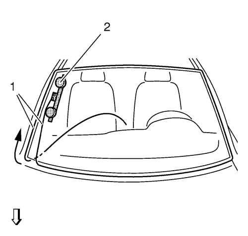
Note: Ensure that the cutting wire is fitted correctly to the winch deflection roller.
- Place the winch with two winding heads (2) on windscreen inside.
| • | Position winch in right-hand area of the windscreen. |
| • | Attach the cutting wire to the winch. |
Note: In the area of the A-pillar/front wall, increased cutting effort must be made.
- Cut out windscreen.
| • | Use the plastic sheet for the protection of the armature board. |
| • | Arrow shows the path taken by the cutting wire (1). |
| • | Insert transfer ratchet and pre-tension cutting wire. |
| • | Cut out the windscreen until the cutting wire is level with the winch. |
Note: Ensure that the cutting wire is fitted correctly to the winch deflection roller.
- Place the winch with two winding heads (2) in the vehicle.
| • | Position the winch near to the interior rear view mirror. |
| • | Insert transfer ratchet and pre-tension cutting wire. |
Note: In the area of the A-pillar/roof frame, increased cutting effort must be made.
- Cut out windscreen.
| • | Use the hold-down positioner and the plastic sheet to protect the sunroof. |
| • | Arrow shows the path taken by the cutting wire (1). |
| • | Cut out the windscreen until the cutting wire is level with the winch. |
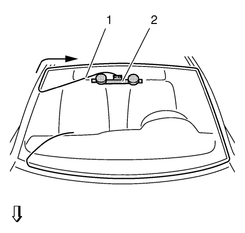
Note: Ensure that the cutting wire is fitted correctly to the winch deflection roller.
- Place the winch with one winding head in the vehicle.
| • | Position the winch with one winding head on the A-pillar on the driver's side (2). |
| • | Attach the cutting wire (1) to the winch. |
| • | Insert transfer ratchet and pre-tension cutting wire. |
Note: Use lubricant on the winch deflection roller. More pulling force is required to cut the area around the A-pillar/bulkhead.
Arrow shows the path taken by the cutting wire.
- Cut out windscreen.
| • | Cut out the windscreen until the cutting wire is level with the winch. |
| • | Use the plastic sheet for the protection of the armature board. |
Note: Ensure that the cutting wire is fitted correctly to the winch deflection roller.
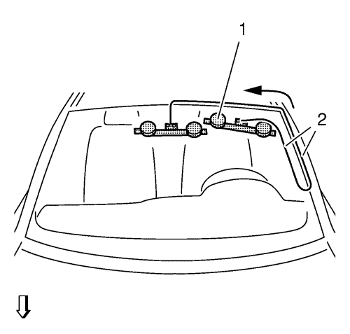
- Place the winch with one winding head in the vehicle.
| • | Position the winch with one winding head in the area of the roof frame (1). |
| • | Insert transfer ratchet and pre-tension cutting wire (2). |
Note: Use lubricant on the winch deflection roller. More pulling force is required to cut the area around the A-pillar/roof frame.
Arrow shows the path taken by the cutting wire.
- Cut out windscreen.
| • | Cut out the windscreen until the cutting wire is level with the winch. |
| • | Use the plastic sheet for the protection of the ceiling. |
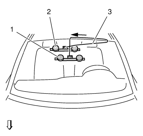
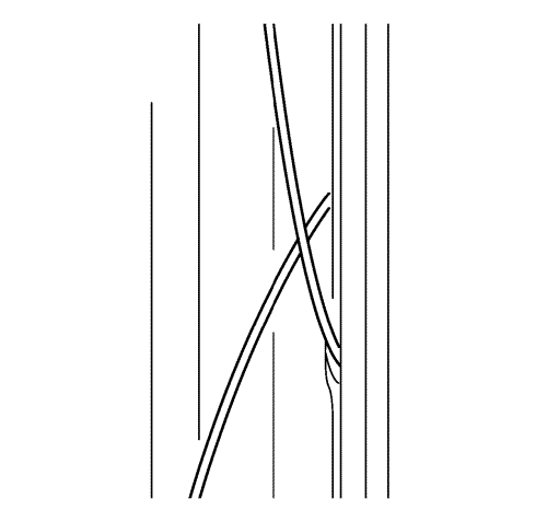
- Position both cutting tools.
| • | Shift winch with two winding heads downwards (1). |
| • | Shift the winch with one winding head (2) in the ceiling area so that the cutting wire (3) is crossed. |
| • | Insert transfer ratchet and pre-tension cutting wire. |
Note: Arrow shows the path taken by the cutting wire.
- Cut out windscreen.
| • | Cut out windscreen until the cutting wire has cut through the adhesive bed completely. |
| • | Use the plastic sheet for the protection of the ceiling. |
- Remove glass removal system.
- Fit and lockBO-641 holder to windscreen.
Note: Second mechanic required.
- Remove windscreen.
- Remove the windscreen upper reveal moulding. Refer to Windscreen Upper Reveal Moulding Replacement .
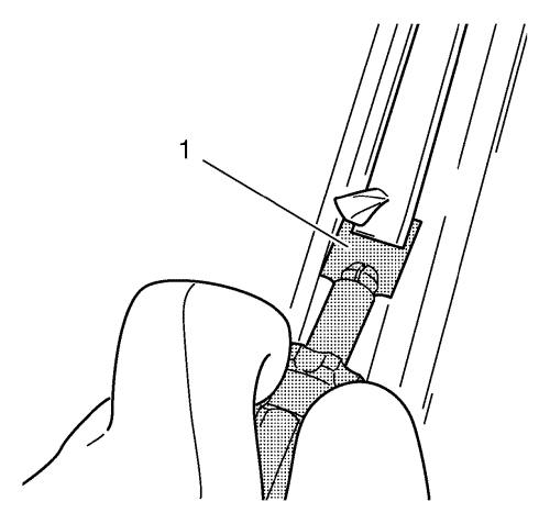
- Cut out the adhesive tape with the knife provided (1) to within 1 mm (0.039 in).
- Repair any paint damage.
Using a touch-up pen to match the colour of the vehicle, repair any paint damage.
- Cut off the adhesive bead on the glass pane
Cut out the adhesive tape with the knife provided (1) to within 1 mm (0.039 in).