Master Cylinder Replacement — Left Hand Drive
Removal Procedure
Warning: Refer to Brake Fluid Irritant Warning in the Preface section.
Caution: Refer to Brake Fluid Effects on Paint and Electrical Components Caution in the Preface section.
- Remove dash upper extension panel opening cover. Refer to Dash Upper Extension Panel Opening Cover Replacement .
- Remove battery tray. Refer to Battery Tray Replacement .
Note: Do NOT disconnect engine coolant hoses.
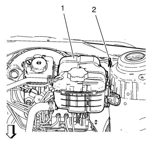
- Remove the radiator surge tank clip (2).
- Remove the radiator expansion tank (1) without draining.
Position the radiator surge tank (1) aside.
- Disconnect the brake fluid level indicator switch electrical connector and separate from brake fluid reservoir.
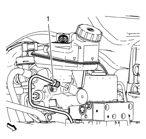
- Disconnect the master cylinder secondary brake pipe fitting (1).
Cap the brake pipe fitting and plug the master cylinder outlet port to prevent brake fluid loss and contamination.
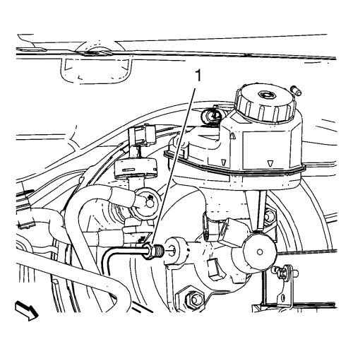
- Disconnect the master cylinder primary brake pipe fitting (1).
Cap the brake pipe fitting and plug the master cylinder outlet port to prevent brake fluid loss and contamination.
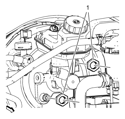
- Remove and DISCARD master cylinder nuts (1).
- Remove master cylinder with brake fluid reservoir.
- Inspect the master cylinder to vacuum brake booster seal for damage and replace, if necessary.
- Remove the master cylinder reservoir, if necessary. Refer to Master Cylinder Reservoir Replacement .
Installation Procedure
- Install the brake fluid reservoir to master cylinder. Refer to Master Cylinder Reservoir Replacement .
- Ensure the master cylinder to vacuum brake booster seal is properly seated on the master cylinder barrel.
- Perform the master cylinder bench bleeding. Refer to Master Cylinder Bench Bleeding .
Warning: Refer to Torque-to-Yield Fastener Warning in the Preface section.
Caution: Refer to Fastener Caution in the Preface section.
- Install NEW master cylinder nuts (1) and tighten to 50 N·m (37 lb ft).
- Install the brake fluid level indicator switch harness to the brake fluid reservoir and connect the electrical connector.
- Connect the master cylinder primary brake pipe fitting (1) and tighten to 18 N·m (13 lb ft).
- Connect the master cylinder secondary brake pipe fitting (1) and tighten to 18 N·m (13 lb ft).
- Install the radiator surge tank (1.)
- Install the radiator surge tank clip (2).
- Install the battery tray. Refer to Battery Tray Replacement .
- Install dash upper extension panel opening cover. Refer to Dash Upper Extension Panel Opening Cover Replacement .
- Bleed the hydraulic brake system. Refer to Hydraulic Brake System Bleeding .
| © Copyright Chevrolet. All rights reserved |
| © Copyright Chevrolet. All rights reserved |


