Caution: Ensure that the steering column dash seal is installed properly onto steering gear rack pinion housing. The sealing lip MUST rest on lower steering column cover surface evenly. To ease installation of the seal, apply liquid soap to the sealing lip. After installation, verify that the seal lip does not protrude into the vehicle's interior. Improper installation could result in poor sealing performance and water intrusion into the vehicle.
Note: Check correct wiring routing in order to assure correct installation.
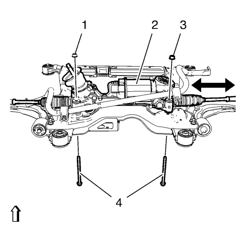
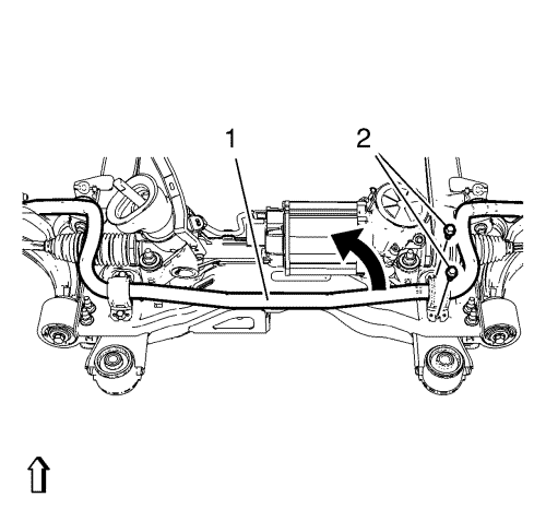
- Carefully insert the steering gear (2) through the right wheel house and position the steering gear into installation position.
Caution: Refer to Fastener Caution in the Preface section.
Caution: Refer to Torque-to-Yield Fastener Caution in the Preface section.
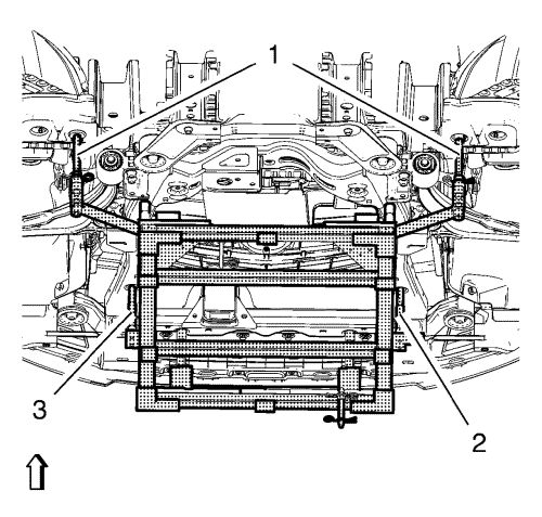
- Tighten the NEW steering gear bolts (4) and nuts (1, 3) a first pass to 110 N·m (81 lb ft).
- Tighten the NEW steering gear bolts and nuts a final pass to an additional 150 to 165 degrees, using the EN-45059 meter .
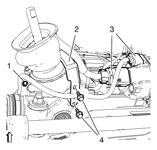
- Install and tighten the 2 wiring harness bracket bolts (4) to 9 N·m (80 lb in).
- Tighten the wiring harness retainer (1) to the steering gear.
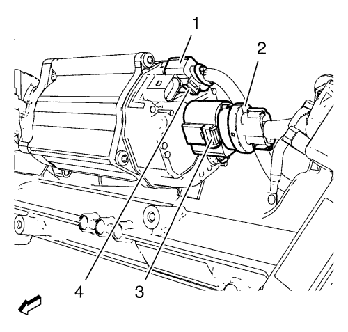
Note: Connector catches are difficult to access.
- Connect the electrical connector (1) until you hear it clicks.
- Connect the electrical connector (2) until you hear it clicks.
Note: Connector catches are difficult to access.
- Connect the electrical connector (3) until you hear it clicks.
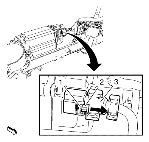
- Push back the lock (2) in opposite direction of the arrow until you hear it clicks.
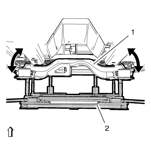
- Position the stabiliser shaft (1) and the bracket onto the suspension frame.
- Install and tighten the NEW right stabilizer shaft insulator clamp bolts (2) a first pass to 22 N·m (16 lb ft).
Caution: Refer to Torque-to-Yield Fastener Caution in the Preface section.
- Tighten the NEW stabilizer shaft insulator clamp bolts a final pass to an additional 30 degrees, using the EN-45059 meter .
- Move out the positioning pins (1) of CH-49289 adapter.
- Raise the frame (1) carefully, using CH-49289 adapter (2).
Note: Do NOT reuse old bolts
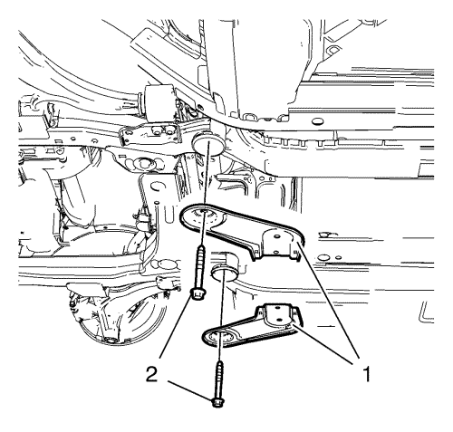
- Install the frame reinforcements (1).
- Install the 2 frame rear bolts (2) and tighten to 160 N·m (118 lb ft).
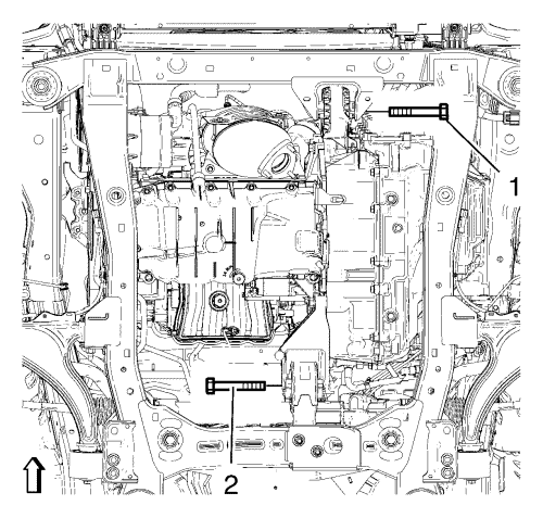
- Install the front transmission mount bolt (1) and tighten to 100 N·m (74 lb ft).
- Install the rear transmission mount bracket bolt (2) and tighten to 100 N·m (74 lb ft).
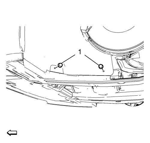
- Install and tighten the 2 fasteners (1) of the engine side cover on both sides.
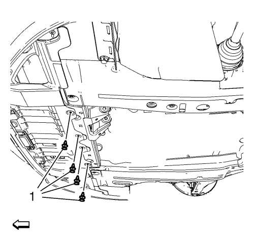
- Install and tighten the 4 fasteners (1) of the front engine compartment cover.
- Install the front compartment insulator, if equipped. Refer to Front Compartment Insulator Replacement .
- Install the exhaust front pipe. Refer to
Exhaust Front Pipe Replacement : 2.0L Diesel LNP → LDE, LLU, LXT, LXV, L2W, 2H0, LFH, LGE .
- Tighten the steering linkage outer track rod to the steering knuckle. Refer to Steering Linkage Outer Track rod Replacement .
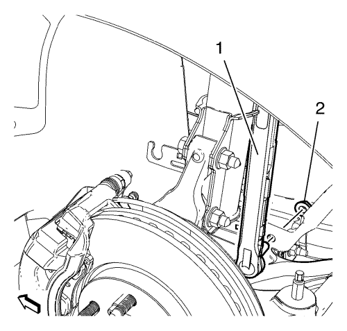
- Install and tighten the lower stabiliser link shaft nut (2) on both sides to 35 N·m (26 lb ft).
- Lower the vehicle.
Caution: Refer to Torque-to-Yield Fastener Caution in the Preface section.
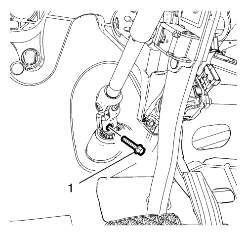
- Install the NEW lower intermediate steering shaft bolt and tighten a first pass to 25 N·m (18 lb ft).
- Tighten the NEW lower intermediate steering shaft bolt a final pass to an additional 180 to 195 degrees, using the EN-45059 meter .
- Install the tyre and wheel assemblies. Refer to Tyre and Wheel Removal and Installation .
- Connect the battery negative cable. Refer to
Battery Negative Cable Disconnection and Connection : without Start/Stop System .
- Check and adjust the wheel alignment. Refer to Wheel Alignment Measurement .
- Centre the steering angle sensor and learn the softened stops. Refer to Power Steering Control Module Calibration .
- Program the power steering control module. Refer to
Power Steering Control Module Programming and Setup : Electronic Power Steering .
- Program volatile memory. Refer to Volatile Memory Programming .


