Caution: Ensure that the steering column dash seal is installed properly onto steering gear rack pinion housing. The sealing lip MUST rest on lower steering column cover surface evenly. To ease installation of the seal, apply liquid soap to the sealing lip. After installation, verify that the seal lip does not protrude into the vehicle's interior. Improper installation could result in poor sealing performance and water intrusion into the vehicle.
- Install the steering gear.
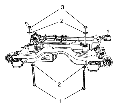
- Install steering gear bolts (1), washers (2) and nuts (3) to the steering gear.
Caution: Refer to Fastener Caution in the Preface section.
Caution: Refer to Torque-to-Yield Fastener Caution in the Preface section.
- Tighten the NEW steering gear bolts a first pass to 110 N·m (81 lb ft).
- Tighten the NEW steering gear bolts a final pass to an additional 150 to 165 degrees, using the EN-45059 meter .
- Raise the frame with the hydraulic jack.
- Install the rear frame to body bolts. Refer to Drivetrain and Front Suspension Frame Replacement .
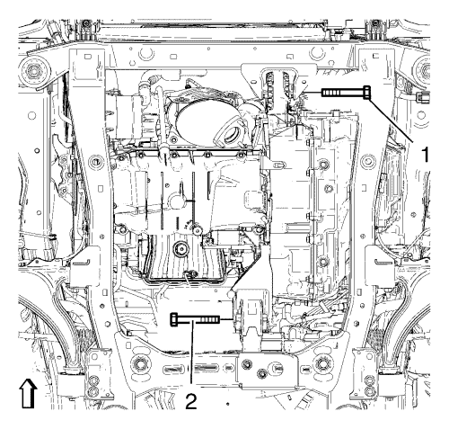
- Install the front transmission mount bolt (1) and tighten to 100 N·m (74 lb ft).
- Install the rear transmission mount bracket bolt (2) and tighten to 100 N·m (74 lb ft).
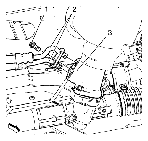
- Replace the O-rings of the inlet and outlet hoses. Lubricate O-rings with a small amount of hydraulic oil.
- Install the inlet and outlet hose (2) to the steering gear (3) and install the power steering gear inlet and outlet hose bolt (1). Tighten the power steering inlet and outlet hose bolt to 11 N·m (97 lb in).
- Install the stabiliser shaft link to the strut.
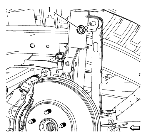
- Install the NEW stabiliser shaft link nut (1) and tighten to 65 N·m (48 lb ft).
- Install the steering linkage inner track rod. Refer to
Steering Linkage Inner Track Rod Replacement : Electronic Power Steering → Hydraulic Power Steering .
- Install the front compartment insulator, if equipped. Refer to Front Compartment Insulator Replacement .
- Install the front compartment splash shield. Refer to Front Compartment Splash Shield Replacement .
- Install the exhaust front pipe. Refer to
Exhaust Front Pipe Replacement : 2.0L Diesel LNP → LDE, LLU, LXT, LXV, L2W, 2H0, LFH, LGE .
- Install the front tyre and wheel assemblies. Refer to Tyre and Wheel Removal and Installation .
- Lower the vehicle.
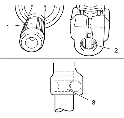
Note: The recess (2) of the fine toothing in the universal joint has to align precisely with the recess (1) of the fine toothing on the steering pinion. The bore in the universal joint have to align with the groove on the steering pinion (3).
- Check alignment of fine toothing of universal joint and steering pinion.
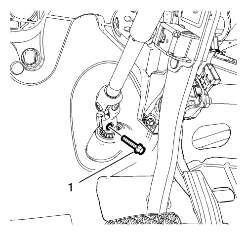
- Install the NEW lower intermediate steering shaft bolt and tighten a first pass to 28 N·m (18 lb ft).
Caution: Refer to Torque-to-Yield Fastener Caution in the Preface section.
- Tighten the NEW lower intermediate steering shaft bolt a final pass to an additional 180 to 195 degrees, using the EN-45059 meter .
- Adjust the front toe. Refer to Wheel Alignment - Steering Wheel Angle and/or Front Toe Adjustment .
- Bleed the hydraulic steering system. Refer to Power Steering System Bleeding .


