To the top of the document
Orlando
   
GMDE Start Page Load static TOC Load dynamic TOC Help?

Steering Column Replacement

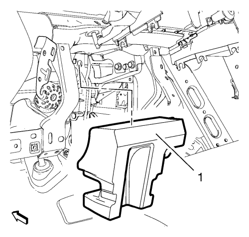
Caution: With wheels of the vehicle facing straight ahead, secure the steering wheel utilizing steering column anti-rotation pin, steering column lock, or a strap to prevent rotation. Locking of the steering column will prevent damage and a possible malfunction of the SIR system. The steering wheel must be secured in position before disconnecting the following components:

   • The steering column
   • The steering shaft coupling
   • The intermediate shaft(s)
After disconnecting these components, do not rotate the steering wheel or move the front tyres and wheels. Failure to follow this procedure may cause the SIR coil assembly to become un-centred and cause possible damage to the SIR coil. If you think the SIR coil has became uncentred, refer to your specific SIR coil's centring procedure to re-centre SIR Coil.

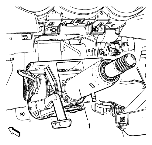
Caution: Once the steering column is removed from the car, the column is extremely susceptible to damage. Dropping the column on its end could collapse the steering shaft or loosen the plastic injections which maintain column rigidity. Leaning on the column could cause the jacket to bend or deform. Any of the above damage could impair the column's collapsible design. If it is necessary to remove the steering wheel, use only the specified steering wheel puller. Under no conditions should the end of the shaft be hammered upon as hammering could loosen plastic injections which maintain column rigidity.

Removal Procedure

  1. Remove the instrument panel lower trim pad cover. Refer to Instrument Panel Lower Trim Pad Cover Replacement .
  2. Remove the intermediate steering shaft. Refer to Intermediate Steering Shaft Replacement .
  3. Remove the inflatable restraint steering wheel module. Refer to Steering Wheel Inflatable Restraint Module Replacement .
  4. Remove the steering wheel. Refer to Steering Wheel Replacement .
  5. Remove the steering column upper trim cover. Refer to Steering Column Upper Trim Cover Replacement .
  6. Remove the steering column lower trim cover. Refer to Steering Column Lower Trim Cover Replacement .
  7. Remove the steering angle sensor. Refer to Steering Angle Sensor Replacement .
  8. Remove the steering inflatable restraint module coil. Refer to Steering Wheel Airbag Coil Replacement .
  9. Remove the indicator switch. Refer to Indicator Switch Replacement .
  10. Remove windscreen wiper and washer switch. Refer to Windscreen Wiper and Washer Switch Replacement .
  11. Remove the turn signal switch bracket. Refer to Turn Signal Switch Bracket Replacement
  12. Remove the ignition and start switch housing. Refer to Ignition and Start Switch Housing Replacement
  13. Disconnect electrical connectors as needed.
  14. Note: Install tie straps between the tilt lever bracket and the base of the steering column to prevent the steering column jacket from pulling apart. The tilt lever MUST be in the LOCK (FULL UP) position during the steering column removal and installation to ensure that the tilt lever bracket remains rigid. Also install tie straps around the tilt lever and the steering column jacket to keep the tilt lever in the LOCK position. Do not bend the steering column energy absorbing straps located on the upper steering column mounting bracket.

  15. Install tie straps as described above.

  16. 2027642
  17. Remove and DISCARD the steering column nuts (1).

  18. 2027643
  19. Remove the steering column (1).

  20. 2538054
  21. Remove the steering column insulator (1) if necessary.

Installation Procedure


    2538054
  1. Install the steering column insulator (1).

  2. 2027643

    Note: 

       • Start all nuts by hand before finalising any torques.
       • Do not bend the steering column energy absorbing straps located on the upper steering column mounting bracket during installation.

  3. Install the steering column (1).
  4. Warning: Refer to Torque-to-Yield Fastener Warning in the Preface section.

    Caution: Refer to Fastener Caution in the Preface section.


    2027642
  5. Install the NEW steering column nuts (1). Tighten the steering column nuts 22 N·m (16 lb ft) + 45°.
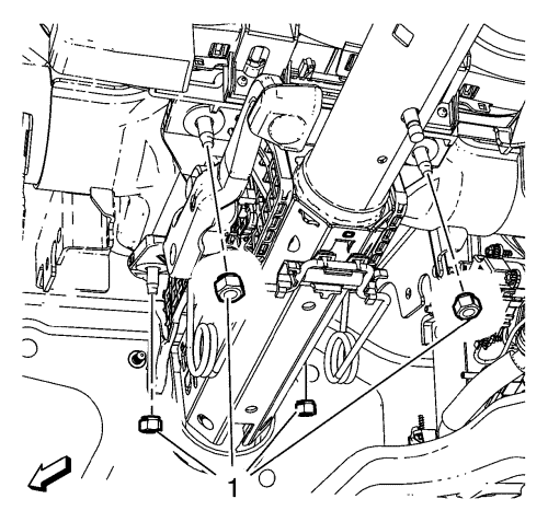
  6. Warning: In order to ensure the intended function of the steering column in a vehicle during a crash and in order to avoid personal injury to the driver, perform the following:

       • Tighten the steering column lower fasteners before you tighten the steering column upper fasteners. Failure to do this can damage the steering column.
       • Tighten the steering column fasteners to the specified torque. Overtightening the upper steering column fasteners could affect the steering column collapse.

  7. Remove the tie straps.
  8. Connect any electrical connectors as needed.
  9. Install the ignition and start switch housing. Refer to Ignition and Start Switch Housing Replacement
  10. Install the turn signal switch bracket. Refer to Turn Signal Switch Bracket Replacement
  11. Install the windshield wiper and washer switch. Refer to Windscreen Wiper and Washer Switch Replacement .
  12. Install the indicator switch. Refer to Indicator Switch Replacement .
  13. Install the steering wheel inflatable restraint module coil. Refer to Steering Wheel Airbag Coil Replacement .
  14. Install the steering angle sensor. Refer to Steering Angle Sensor Replacement .
  15. Install the steering column lower trim cover. Refer to Steering Column Lower Trim Cover Replacement .
  16. Install the steering column upper trim cover. Refer to Steering Column Upper Trim Cover Replacement .
  17. Install the steering wheel. Refer to Steering Wheel Replacement .
  18. Install the steering wheel inflatable restraint module. Refer to Steering Wheel Inflatable Restraint Module Replacement .
  19. Install the intermediate steering shaft. Refer to Intermediate Steering Shaft Replacement .
  20. Install the instrument panel lower trim pad cover. Refer to Instrument Panel Lower Trim Pad Cover Replacement .
  21. Calibrate the steering angle sensor. Refer to Power Steering Control Module Calibration .


© Copyright Chevrolet. All rights reserved


© Copyright Chevrolet. All rights reserved