Stabiliser Shaft Replacement
Special Tools
| • | CH-49289 Centring Frame |
For equivalent regional tools, refer to Special Tools .
Removal Procedure
Caution: With wheels of the vehicle facing straight ahead, secure the steering wheel utilising steering column anti-rotation pin, steering column lock or a strap to prevent rotation. Locking of the steering column will prevent damage and a possible malfunction of the SIR system. The steering wheel must be secured in position before disconnecting the following components:
| • | The intermediate shaft(s) |
- Turn the front wheels to the straight forward position and secure the steering wheel from moving.
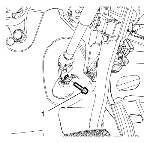
- Remove and DISCARD the lower steering intermediate shaft bolt (1).
- Remove the steering intermediate shaft from the steering gear.
- Raise and support the vehicle. Refer to Lifting and Jacking the Vehicle .
- Remove the tyre and wheel assemblies. Refer to Tyre and Wheel Removal and Installation .
- Remove the front compartment insulator, if equipped. Refer to Front Compartment Insulator Replacement .
- Remove the exhaust front pipe. Refer to
Exhaust Front Pipe Replacement : 2.0L Diesel LNP → LDE, LLU, LXT, LXV, L2W, 2H0, LFH, LGE .
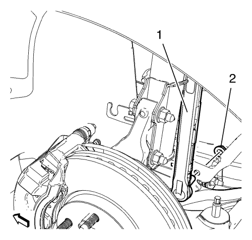
- Remove and DISCARD the lower stabilizer link shaft nut (2) on both sides.
- Remove stabiliser link shaft (1) from stabiliser shaft.
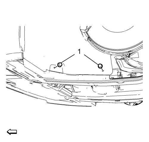
- Remove 2 fasteners (1) of engine side cover on both sides.
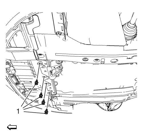
- Remove 4 fasteners (1) of front engine compartment cover.
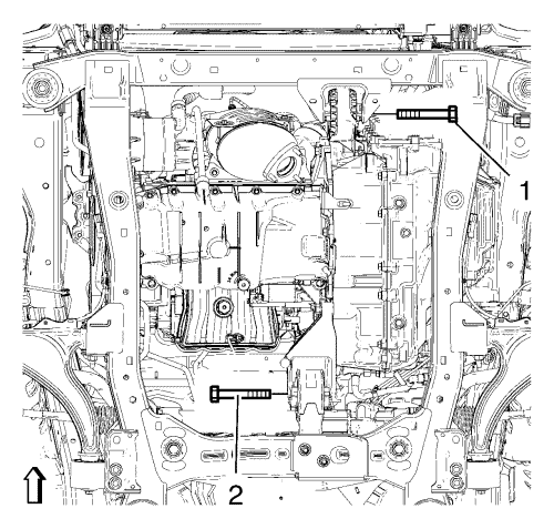
- Remove the front (1) and the rear (2) transmission mount bracket bolts.
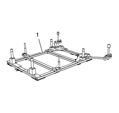
Note: The SPX installation manual is supplied with the special tool and is also available online from SPX directly. Go to www.spxtools-shop.com.
- Assemble the CH-49289 centring frame (1) according to the details provided in the SPX installation manual.
- Support the CH-904 base frame on a jack.
- Support the CH-49289 centring frame on the CH-904 base frame.
- Bent front cover aside.
- Install the CH-49289 centering frame according to the details provided in the SPX installation manual.
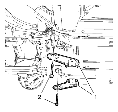
- Remove 2 rear suspension frame bolts (2).
Remove rear frame reinforcements (1).
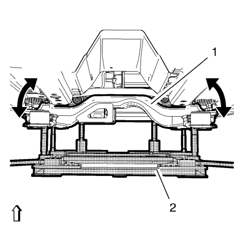
- Lower suspension frame (1) max. 55 mm (2.17 in), using the CH-49289 centering frame (2).
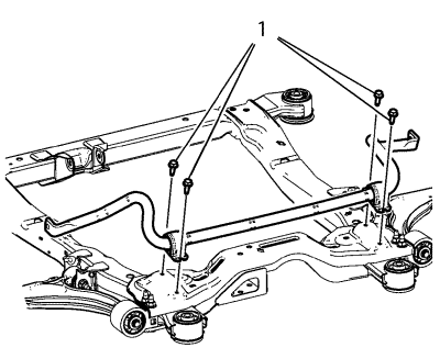
- Remove the 4 front stabiliser shaft insulator clamp bolts (1).
- Remove the stabiliser shaft.
Installation Procedure
- Install the stabiliser shaft.
Caution: Refer to Fastener Caution in the Preface section.
Caution: Refer to Torque-to-Yield Fastener Caution in the Preface section.
- Install the 4 front stabilizer shaft insulator clamp bolts (1) and tighten a first pass to 22 N·m (16 lb ft).
- Tighten the 4 front stabilizer shaft insulator clamp bolts a final pass to an additional 30 to 45 degrees, using the EN-45059 meter.
- Raise the frame (1) carefully, using CH-49289 adapter (2).
- Install the 2 frame reinforcements (1).
- Install the 2 frame rear bolts (2) and tighten to 160 N·m (118 lb ft).
Note: The SPX installation manual is supplied with the special tool and is also available online from SPX directly. Go to www.spxtools-shop.com.
- Lower the CH-49289 centering frame (1) with CH-904 base frame and a jack.
- Remove the CH-49289 centring frame from the CH-904 base frame.
- Disassemble the CH-49289 centering frame according to the details provided in the SPX installation manual.
- Unbend the front cover.
- Install the front and rear transmission mount bracket bolts (1, 2) and tighten to 100 N·m (74 lb ft).
- Install and tighten 2 fasteners (1) of engine side cover on both sides.
- Install and tighten 4 fasteners (1) of front engine compartment cover.
- Install the front compartment insulator, if equipped Front Compartment Insulator Replacement .
- Install the exhaust front pipe. Refer to
Exhaust Front Pipe Replacement : 2.0L Diesel LNP → LDE, LLU, LXT, LXV, L2W, 2H0, LFH, LGE .
- Install and tighten the NEW lower stabilizer link shaft nut (2) on both sides to 65 N·m (48 lb ft).
- Install the tyre and wheel assemblies. Refer to Tyre and Wheel Removal and Installation .
- Lower the vehicle.
- Install the NEW lower intermediate steering shaft bolt and tighten a first pass to 25 N·m (18 lb ft).
Caution: Refer to Torque-to-Yield Fastener Caution in the Preface section.
- Tighten the NEW lower intermediate steering shaft bolt a final pass to an additional 180 degrees, using the EN-45059 meter.
| © Copyright Chevrolet. All rights reserved |
| © Copyright Chevrolet. All rights reserved |


