Rear Axle Replacement
Special Tools
EN-45059 Torque Angle Sensor Kit
For equivalent regional tools, refer to Special Tools .
Removal Procedure
- Raise and suitably support the vehicle. Refer to Lifting and Jacking the Vehicle .
- Remove the tyre and wheel assembly. Refer to Tyre and Wheel Removal and Installation .
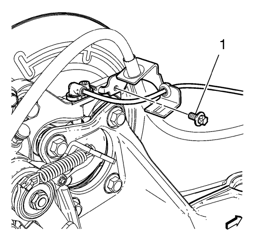
- Remove the both brake hose bolts (1) attaching the hose to the rear brake calliper bracket.
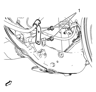
- Remove the 2 rear parking brake cable bracket bolts (1) from the rear axle.
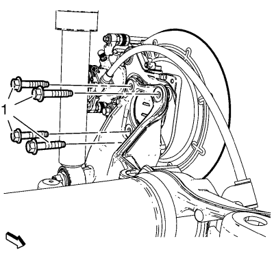
- Remove the 4 wheel bearing/hub mounting bolts (1).
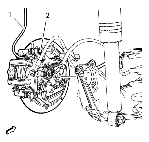
Caution: Support the brake calliper with heavy mechanic wire, or equivalent, whenever it is separated from its mount and the hydraulic flexible brake hose is still connected. Failure to support the calliper in this manner will cause the flexible brake hose to bear the weight of the calliper, which may cause damage to the brake hose and in turn may cause a brake fluid leak.
- Without disconnecting the hydraulic brake flexible hose, remove wheel bearing/hub and brake assembly (2) upward and secure the wheel bearing/hub and brake assembly with heavy mechanics wire (1), or equivalent.
- Support the rear axle with a hydraulic lift table.
- Remove the lower shock bolts. Refer to Shock Absorber Replacement .
- Lower the hydraulic lift table and remove the rear coil springs. Refer to Rear Spring Replacement .
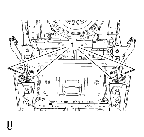
- Remove both rear axle bushing bolts and nuts (1).
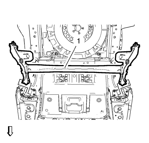
- Use the hydraulic lift table to lower the rear axle (1) from the vehicle.
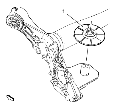
- Remove the rear coil spring lower seat insulators (1) from the axle.
Installation Procedure
- Install the rear coil spring lower seat insulators (1) to the axle.
- Raise the axle (1) into position.
- Loosely install the both axle bushing bolts and nuts (1).
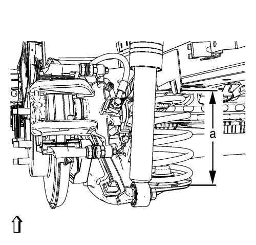
Note: The axle bushing bolts and nuts must be tightened with the axle at the correct trim height.
- Using the lift table, raise the axle to the proper trim height specification by measuring the vertical distance between the bottom edge of the upper spring seat and the bottom of the notch in the lower spring seat specification:
Specification
Dimension (a): 224 mm (8.82 in)
Caution: Refer to Fastener Caution in the Preface section.
- Tighten the NEW axle bushing through bolts and NEW nuts and tighten to 70 N·m (52 lb ft) + 130°, using the EN-45059 kit.
- Install the rear coil springs. Refer to Rear Spring Replacement .
- Install the lower shock bolts. Refer to Shock Absorber Replacement .
- Remove the hydraulic lift table from the rear axle.
- Install the wheel bearing/hub and brake assembly.
- Install the 4 NEW wheel bearing/hub mounting bolts (1) and tighten to 50 N·m (37 lb ft) + 40°, using the EN-45059 kit.
- Install the 2 rear parking brake cable bracket bolts (1) at the rear axle and tighten to 10 N·m (89 lb in).
- Install both brake hose bolts (1) attaching the hose to the rear brake calliper bracket.
- Install the tyre and wheel assembly. Refer to Tyre and Wheel Removal and Installation .
- Lower the vehicle.
| © Copyright Chevrolet. All rights reserved |
| © Copyright Chevrolet. All rights reserved |


