To the top of the document
Orlando
   
GMDE Start Page Load static TOC Load dynamic TOC Help?

Charge Air Cooler Outlet Hose Replacement - LNP and Automatic Transmission

Removal Procedure

  1. Remove the engine sight shield. Refer to Engine Sight Shield Replacement .
  2. Remove the battery tray. Refer to Battery Tray Replacement .
  3. Remove the engine control module. Refer to Engine Control Module Replacement .
  4. Remove the radiator surge tank. Refer to Radiator Surge Tank Replacement .
  5. Unclip the engine wiring harness retaining clip from the charge air cooler outlet front hose.
  6. Unclip the transmission vent hose from the charge air cooler outlet front hose.

  7. 2511669
  8. Remove the charge air cooler outlet front hose bracket bolt (2).
  9. Loosen the charge air cooler outlet front hose to rear hose clip (4).
  10. Detach the charge air cooler outlet front hose (1) along with the clamp (4) from the charge air cooler outlet rear hose (3).

  11. 2511666
  12. Unclip the 2 wiring harness retaining clips from the charge air cooler outlet rear hose (2).
  13. Place a suitable tool at the rebate (1) and rotate the lock ring anti-clockwise.
  14. Detach the charge air cooler outlet rear hose (2) from the throttle body (3).
  15. Remove the charge air cooler outlet rear hose (2).

  16. 2511649
  17. Disconnect the exhaust temperature sensor wiring harness plug (5).
  18. Unclip the heated oxygen sensor wiring harness plug (3) from the retainer clip (4) and disconnect the heated oxygen sensor wiring harness plug (3).
  19. Disconnect the exhaust pressure differential sensor hose wiring harness plug (2).
  20. Unclip the engine wiring harness retaining clip from the charge air cooler outlet front hose.
  21. Unclip the transmission vent hose from the charge air cooler outlet front hose.

  22. 2511659
  23. Unclip the 2 wiring harness clips (1) from the wiring harness bracket.
  24. Remove the upper radiator brackets. Refer to Radiator Upper Bracket Replacement .
  25. Remove the inlet air duct. Refer to Inlet Air Duct Replacement .
  26. Remove the left radiator protector fender from the radiator.
  27. Remove the charge air cooler inlet and outlet hose from the charge air cooler.

  28. 2191506
  29. Remove the power steering fluid cooling pipe loop bracket bolts (2).
  30. Hang the power steering fluid cooling pipe loop aside.

  31. 2538012

    Note: Move the radiator forward to remove the charge air cooler outlet hose.

  32. Remove the charge air cooler outlet hose (1) downwards from the vehicle.

Installation Procedure


    2538012

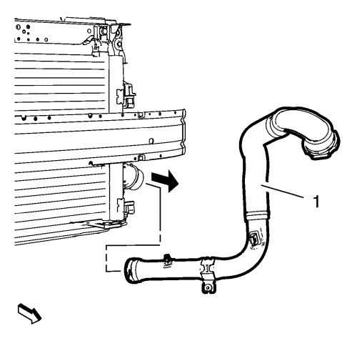
    Note: Move the radiator forward to install the charge air cooler outlet hose.

  1. Position the charge air cooler outlet hose (1) to the vehicle.
  2. Caution: Refer to Fastener Caution in the Preface section.


    2191506
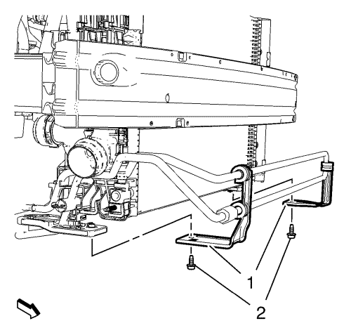
  3. Install the power steering fluid cooling pipe loop.
  4. Install the 2 power steering fluid cooling pipe loop bracket bolts (2) and tighten to 9 N·m (80 lb in).
  5. Install the charge air cooler inlet and outlet hose to the charge air cooler.
  6. Install the left radiator protector wing to the radiator.
  7. Install the radiator upper brackets. Refer to Radiator Upper Bracket Replacement .
  8. Install the inlet air duct. Refer to Inlet Air Duct Replacement .

  9. 2511666

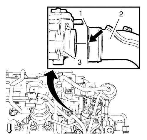
    Note: Make sure that the retaining ring is locked.

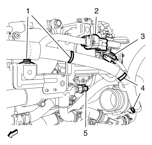
  10. Install the charge air cooler outlet rear hose (2) to the throttle body (3).
  11. Clip in the 2 wiring harness retaining clips to the charge air cooler outlet rear hose (2).

  12. 2511669
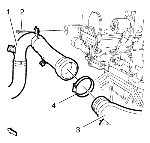
  13. Install the charge air cooler outlet front hose (1) along with the clamp (4) to the charge air cooler outlet rear hose (3).
  14. Caution: Refer to Fastener Caution in the Preface section.

  15. Install the charge air cooler outlet front hose bracket bolt (2) and tighten to 9 N·m (80 lb in).
  16. Tighten the charge air cooler outlet front hose to rear hose clip (4) to 4 N·m (35 lb in).
  17. Clip in the engine wiring harness retaining clip to the charge air cooler outlet front hose.

  18. 2511659
  19. Clip in the 2 wiring harness clips (1) to the wiring harness bracket.

  20. 2511649
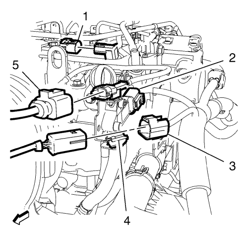
  21. Connect the exhaust temperature sensor wiring harness plug (5).
  22. Clip the heated oxygen sensor wiring harness plug (3) to the retainer clip (4) and connect the heated oxygen sensor wiring harness plug (3).
  23. Connect the exhaust pressure differential sensor hose wiring harness plug (2).
  24. Clip in the transmission vent hose to the charge air cooler outlet front hose.
  25. Install the radiator surge tank. Refer to Radiator Surge Tank Replacement .
  26. Install the engine control module. Refer to Engine Control Module Replacement .
  27. Install the battery tray. Refer to Battery Tray Replacement .
  28. Install the engine sight shield. Refer to Engine Sight Shield Replacement .


© Copyright Chevrolet. All rights reserved


© Copyright Chevrolet. All rights reserved