Disconnect the battery negative cable. Refer to
Battery Negative Cable Disconnection and Connection : without Start/Stop System .
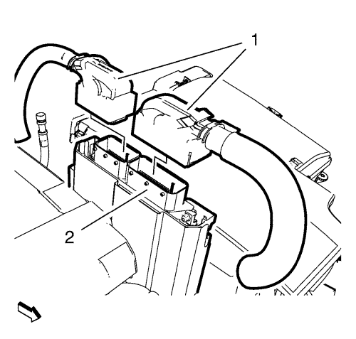
Disconnect the 2 engine control module wiring harness plugs (1) from the engine control module (2).
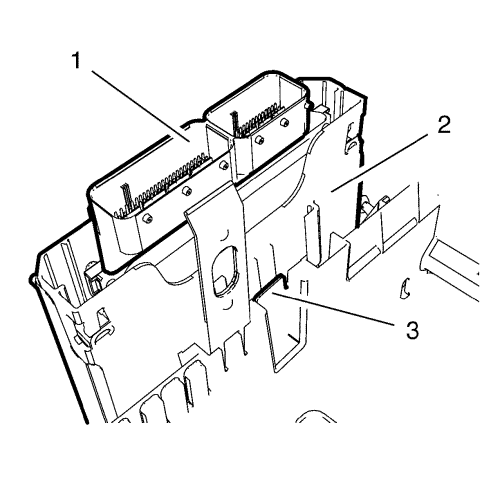
Remove the engine control module bracket (2) along with the engine control module (1) from the battery tray (3).
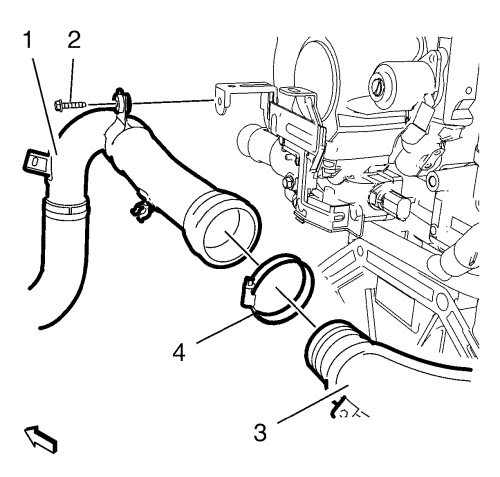
Remove the charge air cooler outlet front hose bracket bolt (2).
Loosen the charge air cooler outlet front hose to rear hose clip (4).
Detach the charge air cooler outlet front hose (1) along with the rear hose clip (4) from the charge air cooler outlet rear hose (3). Hang the charge air cooler outlet hose aside (1).
Disconnect the exhaust pressure differential wiring harness plug.
Disconnect the engine wiring harness from the glow plug wiring harness plug.
Unclip the engine wiring harness from the wiring harness bracket.
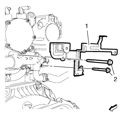
Remove the 2 engine wiring harness bracket and engine water outlet adaptor bolts (2) from the engine water outlet adaptor.
Remove the engine wiring harness bracket (1) from the engine water outlet adaptor.
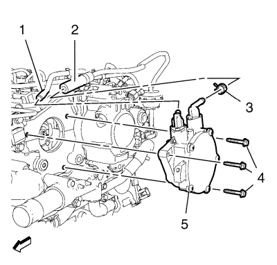
Remove the vacuum pump hose (1).
Loosen the brake servo unit vacuum pipe clamp (3) and remove the brake servo unit vacuum pipe (2).
Remove the 3 vacuum pump assembly bolts (4).
Remove the vacuum pump assembly (5) and the vacuum pump assembly gasket.
Install the 3 vacuum pump assembly bolts (4) and tighten to 10 N·m (89 lb in).
Install the brake servo unit vacuum pipe (2) and fix the brake servo unit vacuum pipe clamp (3).
Install the vacuum pump hose (1).
Install the engine wiring harness bracket (1) to the engine water outlet adaptor.
Install the 2 engine wiring harness bracket and engine water outlet adaptor bolts (2) to the engine water outlet adaptor and tighten to 10 N·m (89 lb in).
Clip the engine wiring harness to the wiring harness bracket.
Connect the engine wiring harness to the glow plug wiring harness plug.
Connect the exhaust pressure differential wiring harness plug.
Install the charge air cooler outlet front hose (1) along with the rear hose clip (4) to the charge air cooler outlet rear hose (3).
Tighten the charge air cooler outlet front hose to the rear hose clip (4) to 4 N·m (35 lb in).
Install the charge air cooler outlet front hose bracket bolt (2) and tighten to 9 N·m (80 lb in).
Install the engine control module bracket (2) along with the engine control module (1) to the battery tray (3).
Connect the 2 engine control module wiring harness plugs (1) to the engine control module (2).
Connect the battery negative cable. Refer to
Battery Negative Cable Disconnection and Connection : without Start/Stop System .