Exhaust Gas Recirculation Valve Cooler Replacement
Removal Procedure
- Remove the engine sight shield. Refer to Engine Sight Shield Replacement .
- Remove the dash upper extension panel opening cover. Refer to Dash Upper Extension Panel Opening Cover Replacement .
- Remove the battery tray. Refer to Battery Tray Replacement .
- Raise and support the vehicle. Refer to Lifting and Jacking the Vehicle .
- Drain the cooling system. Refer to Cooling System Draining and Filling .
- Remove the exhaust gas recirculation pipe. Refer to Exhaust Gas Recirculation Pipe Replacement .
- Lower the vehicle.
- For vehicles with MT: Disconnect the transmission gear lever and selector cable from the transmission. Refer to Manual Gearbox Gear Lever and Selector Lever Cable Replacement .
For vehicles with AT: Disconnect the range selector lever cable from the automatic transmission. Refer to Range Selector Lever Cable Replacement .
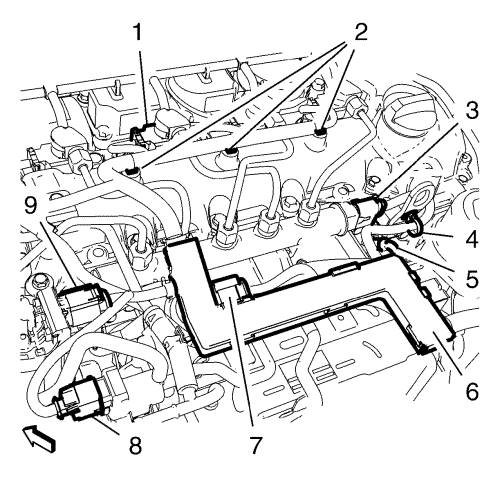
- Disconnect the vacuum solenoid valve wiring harness plug (8).
- Disconnect the exhaust gas recirculation valve wiring harness plug (9).
- Disconnect the inlet actuator valve wiring harness plug (7).
- Disconnect the fuel injection rail pressure sensor wiring harness plug (3).
- Disconnect the 4 glow plug wiring harness plugs (5).
- Disconnect the 4 fuel injector wiring harness plugs (1).
- Unclip the 4 engine wiring harness clips (2, 4) from the camshaft cover.
- Unclip the engine wiring harness conduit (6) in top direction from the 3 exhaust gas recirculation cooler brackets. Hang the engine wiring harness aside.
- Remove the engine coolant air bleed hose. Refer to
Engine Coolant Air Bleed Hose Replacement : 2.0L Diesel LNP .
- Remove the vacuum pump hose. Refer to Vacuum Pump Hose Replacement .
- Remove the inlet manifold tuning valve vacuum control solenoid valve hose. Refer to Inlet Manifold Tuning Valve Vacuum Control Solenoid Valve Hose Replacement .
- Unclip the engine wiring harness retaining clip from the charge air cooler outlet front hose.
- Unclip the transmission vent hose from the charge air cooler outlet front hose.
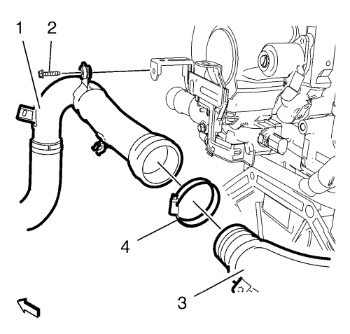
- Remove the charge air cooler outlet front hose bracket bolt (2).
- Loosen the charge air cooler outlet front hose to rear hose clip (4).
- Detach the charge air cooler outlet front hose (1) along with the clamp (4) from the charge air cooler outlet rear hose (3).
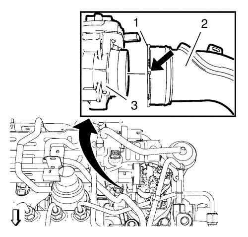
- Unclip the 2 wiring harness retaining clips from the charge air cooler outlet rear hose (2).
- Place a suitable tool at the marked position (arrow) and rotate the lock ring (1) anti-clockwise.
- Detach the charge air cooler outlet rear hose (2) from the throttle body (3).
- Remove the charge air cooler outlet rear hose (2).
- Remove the exhaust gas recirculation manifold cooling return hose. Refer to
Exhaust Gas Recirculation Manifold Cooling Return Hose Replacement : 2.0L Diesel LNP .
- Remove the exhaust gas recirculation cooling feed hose. Refer to Exhaust Gas Recirculation Valve Cooling Feed Hose Replacement .
- Remove the turbocharger coolant return pipe from the exhaust gas recirculation cooler. Refer to Turbocharger Coolant Return Pipe Removal .
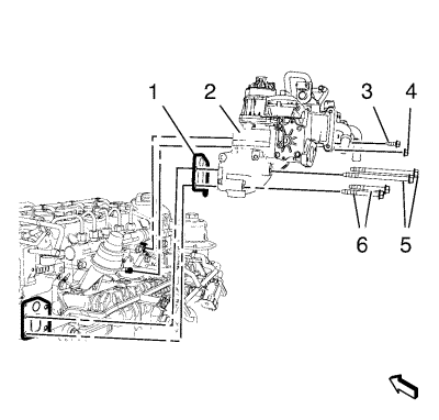
- Remove the exhaust gas recirculation cooler nut (5) and the 5 exhaust gas recirculation cooler bolts (3, 4 and 6).
- Remove the exhaust gas recirculation cooler (2) and the gasket (1).
Installation Procedure
- Install the exhaust gas recirculation cooler (2) and a NEW gasket (1).
Caution: Refer to Fastener Caution in the Preface section.
- Install the 5 exhaust gas recirculation cooler bolts (3, 4 and 6) and the exhaust gas recirculation cooler nut (5) and tighten to 25 N·m (18 lb ft).
- Install the turbocharger coolant return pipe to the exhaust gas recirculation cooler. Refer to Turbocharger Coolant Return Pipe Removal .
- Install the exhaust gas recirculation cooling feed hose. Refer to Exhaust Gas Recirculation Valve Cooling Feed Hose Replacement .
- Install the exhaust gas recirculation manifold cooling return hose. Refer to
Exhaust Gas Recirculation Manifold Cooling Return Hose Replacement : 2.0L Diesel LNP .
Note: Note: Ensure that the retaining ring (1) is locked.
- Install the charge air cooler outlet rear hose (2) to the throttle body (3).
- Clip in the 2 wiring harness retaining clips to the charge air cooler outlet rear hose (2).
- Install the charge air cooler outlet front hose (1) along with the clamp (4) to the charge air cooler outlet rear hose (3).
- Install the charge air cooler outlet front hose bracket bolt (2) and tighten to 9 N·m (80 lb in).
- Tighten the charge air cooler outlet front hose to rear hose clip (4) to 4 N·m (35 lb in).
- Clip in the transmission vent hose to the charge air cooler outlet front hose.
- Clip in the engine wiring harness retaining clip to the charge air cooler outlet front hose.
- Install the inlet manifold tuning valve vacuum control solenoid valve hose. Refer to Inlet Manifold Tuning Valve Vacuum Control Solenoid Valve Hose Replacement .
- Install the vacuum pump hose. Refer to Vacuum Pump Hose Replacement .
- Install the engine coolant air bleed hose. Refer to
Engine Coolant Air Bleed Hose Replacement : 2.0L Diesel LNP .
- Position the engine wiring harness on the vehicle.
- Clip the engine wiring harness conduit (6) to the 3 exhaust gas recirculation cooler brackets.
- Clip the 4 engine wiring harness clips (2, 4) to the camshaft cover.
- Connect the 4 fuel injector wiring harness plugs (1).
- Connect the fuel injection rail pressure sensor wiring harness plug (3).
- Connect the 4 glow plug wiring harness plugs (5).
- Connect the inlet actuator valve wiring harness plug (7).
- Connect the exhaust gas recirculation valve wiring harness plug (9).
- Connect the vacuum solenoid valve wiring harness plug (8).
- For vehicles with MT: Connect the transmission gear lever and selector cable from the transmission. Refer to Manual Gearbox Gear Lever and Selector Lever Cable Replacement .
For vehicles with AT: Connect the range selector lever cable from the automatic transmission. Refer to Range Selector Lever Cable Replacement .
- Raise the vehicle.
- Install the exhaust gas recirculation pipe. Refer to Exhaust Gas Recirculation Pipe Replacement .
- Fill the engine cooling system. Refer to Cooling System Draining and Filling .
- Lower the vehicle.
- Install the battery tray. Refer to Battery Tray Replacement .
- Install the dash upper extension panel opening cover. Refer to Dash Upper Extension Panel Opening Cover Replacement .
- Install the engine sight shield. Refer to Engine Sight Shield Replacement .
| © Copyright Chevrolet. All rights reserved |
| © Copyright Chevrolet. All rights reserved |


