Floor Panel Number 6 Cross Bar Replacement - Brazing
Note : According to different corrosion warranties, only the regional mandatory joining methods are allowed.
Removal Procedure
Warning : Refer to Approved Equipment for Collision Repair Warning in the Preface section.
Warning : Refer to Collision Sectioning Warning in the Preface section.
Warning : Refer to Glass and Sheet Metal Handling Warning in the Preface section.
- Disable the SIR system. Refer to SIR Disabling and Enabling .
- Disconnect the battery negative cable. Refer to
Battery Negative Cable Disconnection and Connection : without Start/Stop System .
- Remove all related panels and components.
- Visually inspect the damage. Repair as much of the damage as possible.
- Remove the sealers and anti-corrosion materials from the repair area as necessary. Refer to
Anti-Corrosion Treatment and Repair : Base .
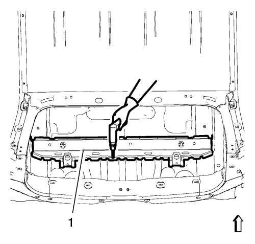
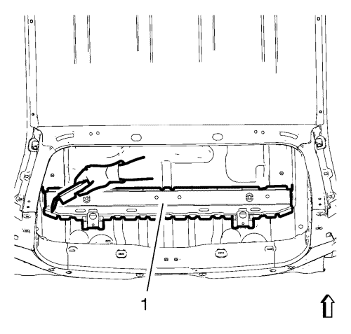
- Locate and mark all the necessary factory welds of the floor panel number 6 cross bar (1).
- Drill all factory welds. Note the number and location of welds for installation of the service assembly.
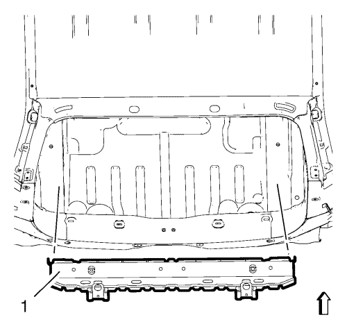
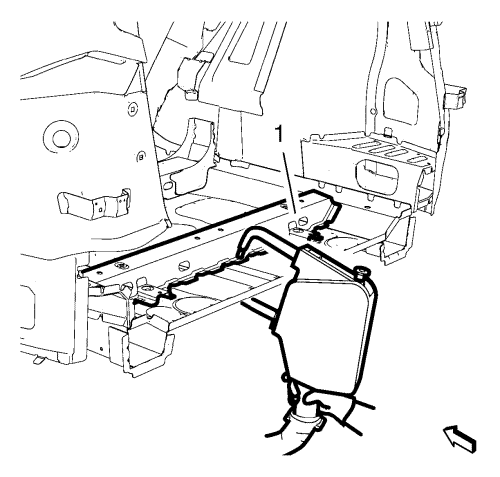
- Remove the damaged floor panel number 6 cross bar (1).
Installation Procedure
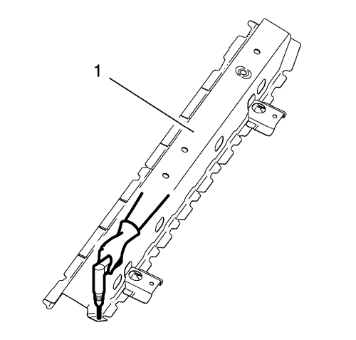
- Create 6x20 mm (4/16 x 12/16 in) slots for brazing along the edges of the floor panel number 6 cross bar (1) where the spotwelder cannot be applied spaced apart every 40 mm (1 ½ in).
- Clean and prepare the attaching surfaces for spotwelding and brazing.
- Apply structural adhesive (1).
- Position the floor panel number 6 cross bar (1).
- Verify the fit of the panel. Refer to Dimensions - Body .
- Clamp the floor panel number 6 cross bar into position.
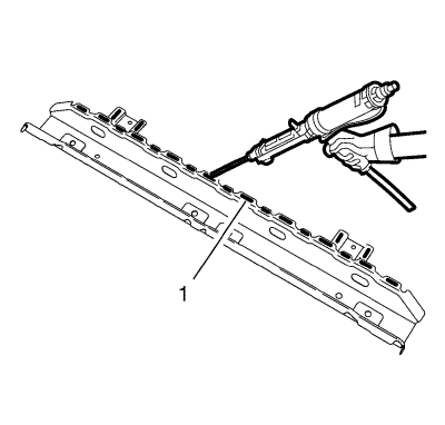
- Braze the floor panel number 6 cross bar (1) accordingly.
- Spotweld the floor panel number 6 cross bar (1) accordingly.
- Apply the sealers and anti-corrosion materials to the repair area, as necessary. Refer to
Anti-Corrosion Treatment and Repair : Base .
- Paint the repaired area.
- Install all related panels and components.
- Connect the battery negative cable. Refer to
Battery Negative Cable Disconnection and Connection : without Start/Stop System .
- Enable the SIR system. Refer to SIR Disabling and Enabling .
| © Copyright Chevrolet. All rights reserved |
| © Copyright Chevrolet. All rights reserved |


