Orlando
Turbocharger Coolant Return Pipe Replacement - 2.0L Diesel LNP
Removal Procedure
Disconnect the battery negative cable. Refer to
Battery Negative Cable Disconnection and Connection
:
without Start/Stop System
.
Remove the engine sight shield. Refer to
Engine Sight Shield Replacement
.
Unclip the fuel injection fuel return hose (2) from the positive crankcase ventilation valve.
Unclip the fuel return hose from the 2 retainer clips.
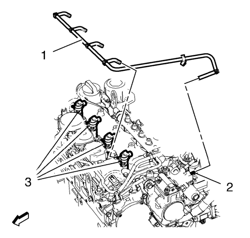
Remove the fuel injection fuel return hose (1) from the fuel injection pump (2) and the fuel injectors (3).
Remove the fuel injection fuel return hose (1).
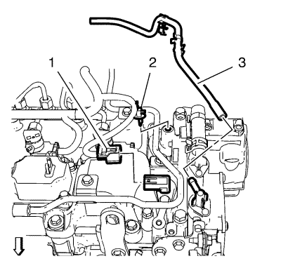
Unclip and remove the vacuum hose (3) from the vacuum pump.
Disconnect the camshaft position sensor wiring harness plug (1).
Unclip the camshaft position sensor wiring harness retaining clip (2) and hang the wiring harness aside.
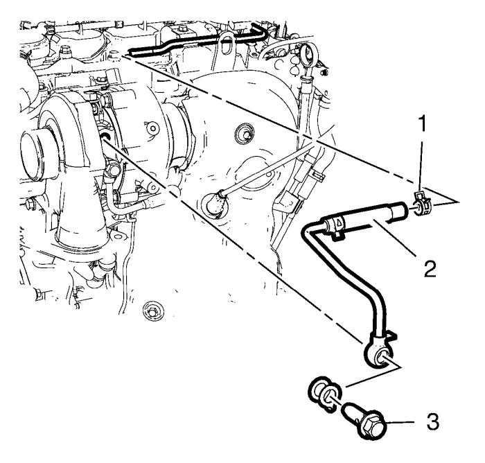
Remove the banjo bolt (3) from the turbocharger.
Remove the clamp (1) from the turbocharger coolant return front pipe (2).
Remove the turbocharger coolant return front pipe (2).
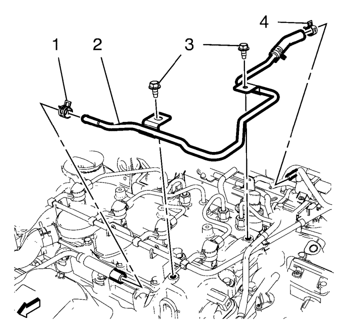
Remove the clamp (4) from the turbocharger coolant return rear pipe (2).
Remove the 2 bolts (3) from the camshaft cover.
Remove the turbocharger coolant return rear pipe (2).
Installation Procedure
Install the turbocharger coolant return rear pipe (2).
Caution:
Refer to
Fastener Caution
in the Preface section.
Install the 2 turbocharger coolant return pipe bracket bolts (3) and tighten to
10 N·m (89 lb in)
.
Install both clamps (1, 4) to the turbocharger coolant return rear pipe (2).
Install the turbocharger coolant return pipe (2).
Install the banjo bolt (3) to the turbocharger coolant return pipe (2) with a NEW gasket and tighten to
32 N·m (24 lb ft)
.
Install the clamp (1) to the turbocharger coolant return pipe (2).
Clip in the camshaft position sensor wiring harness retaining clip (2).
Connect the camshaft position sensor wiring harness plug (1).
Install the vacuum hose (3) to the vacuum pump and clip in the vacuum hose retainer.
Install the fuel injection fuel return hose (1) to the fuel injection pump (2) and the fuel injectors (3).
Clip the fuel return hose into the 2 retainer clips.
Clip the fuel injection fuel return hose (2) to the positive crankcase ventilation valve.
Install the engine sight shield. Refer to
Engine Sight Shield Replacement
.
Connect the battery negative cable. Refer to
Battery Negative Cable Disconnection and Connection
:
without Start/Stop System
.
© Copyright Chevrolet. All rights reserved
© Copyright Chevrolet. All rights reserved