Front Brake Rotor Replacement
Special Tools
| • | CH-41013 Rotor Surfacing Kit |
| • | CH-42450-A Wheel Hub Resurfacing Kit |
For equivalent regional tools, refer to Special Tools .
Warning: Refer to Brake Dust Warning in the Preface section.
Removal Procedure
Caution: Refer to Vehicle Lifting and Jacking Caution in the Preface section.
- Raise and support the vehicle.
- Remove the tire and wheel assembly. Refer to Tire and Wheel Removal and Installation .
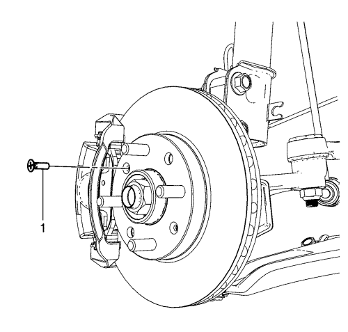
- Remove the brake rotor screw (1).
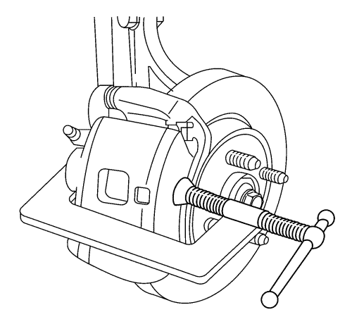
- Install a C-clamp over the body of the brake calliper, with the C-clamp ends against the rear of the calliper body and the outboard disc brake pad.
- Tighten the C-clamp until the calliper piston is compressed into the calliper bore enough to allow the calliper to slide past the brake rotor.
- Remove the C-clamp.
- Remove the brake calliper and the calliper mounting bracket as an assembly from the steering knuckle and support the assembly with heavy mechanics wire or equivalent. Ensure that there is no tension on the hydraulic brake flexible hose. Refer to Front Brake Caliper Bracket Replacement .
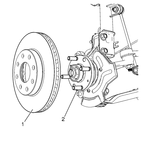
- Remove the brake rotor (1) from the hub flange (2).
Installation Procedure
Note: Whenever the brake rotor has been separated from the hub/axle flange, any rust or contaminants should be cleaned from the hub/axle flange and the brake rotor mating surfaces. Failure to do this may result in excessive assembled lateral runout (LRO) of the brake rotor, which could lead to brake pulsation.
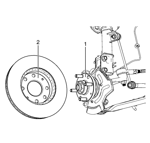
- Using the CH-42450-A wheel hub resurfacing kit, thoroughly clean any rust or corrosion from the mating surface of the hub flange (1).
- Using the CH-41013 rotor resurfacing kit, thoroughly clean any rust or corrosion from the mating surface and mounting surface of the brake rotor (2).
- Inspect the mating surfaces of the hub/axle flange and the rotor to ensure that there are no foreign particles or debris remaining.
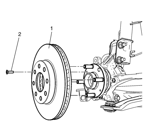
- Install the brake rotor (1) to the hub/axle flange.
Caution: Refer to Fastener Caution in the Preface section.
- Install the brake rotor screw (2) and tighten to 4 N·m (35 lb in).
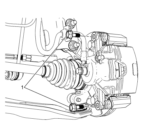
- Remove the support, and install the brake calliper and the brake calliper bracket as an assembly to the steering knuckle and install the brake calliper bracket bolts (1). Refer to Front Brake Caliper Bracket Replacement .
- Install the tyre and wheel assembly. Refer to Tire and Wheel Removal and Installation .
- Lower the vehicle.
- If the brake rotor was refinished or replaced, or if new brake pads were installed, burnish the pads and rotors. Refer to Brake Pad and Rotor Burnishing .
| © Copyright Chevrolet. All rights reserved |


