To the top of the document
Spark
   
GMDE Start Page Load static TOC Load dynamic TOC Help?

1-2-Reverse Clutch Piston Assemble

Special Tools

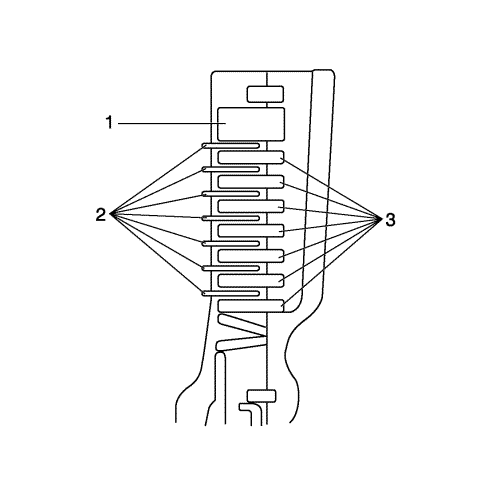
DT-47526 Low and Reverse Brake Spring Compressor

For equivalent regional tools, refer to Special Tools .


    2309097

    Note: 

       • Apply automatic transmission fluid (ATF) to the new O-rings.
       • Be careful not to twist or misalign the O-rings when inserting the low and reverse brake piston.

  1. Replace the O-rings (1, 2) with new ones, then install them to the low and reverse brake piston (3).
  2. Install the low and reverse brake piston.

  3. 2309076

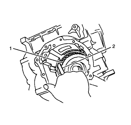
    Note: Be careful not to distort the spring retainer assembly when pressing it into position using DT-47526 low and reverse brake spring compressor.
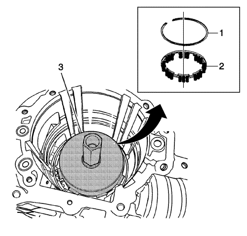
    Note: 

       • Ensure that the circlip fits snugly into the drum groove.
       • Ensure that the circlip opening is not aligned with the stopper.
       • Ensure that the circlip opening is aligned with the concave aperture.

  4. Install the spring retainer assembly (2).
  5. Press the spring retainer assembly using the DT-47526 low and reverse brake spring compressor (3) and install the circlip (1).

  6. 2309069

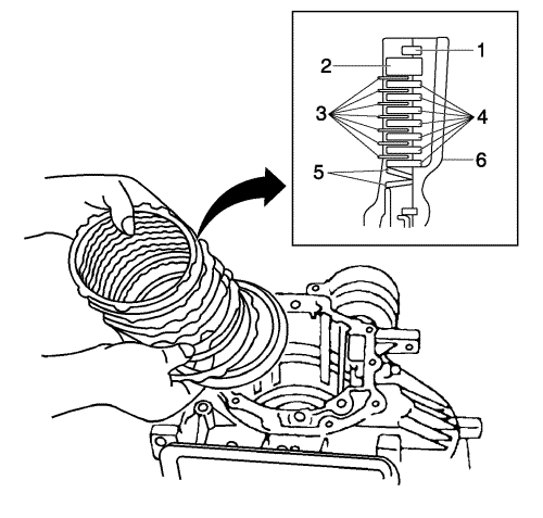
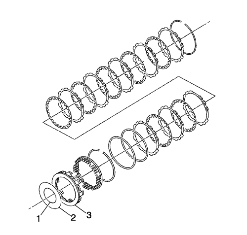
    Note: Before using a new low and reverse brake plate set, soak it in ATF for more than 2 hours.

    Note: Note the direction of the cushion plate.

  7. Assemble with the cushion plate periphery touching the low reverse clutch.
  8. Install the 2 cushion plates (5), 7 separator plates (4), 7 friction plates (3) and the retaining plate (2) to the transmission case (6).
  9. Install the snap ring (1).

  10. 2309106
  11. Using a thickness gauge (2), measure the clearance between the circlip and the retaining plate from the low and reverse brake (1).
  12. Clearance Specification

        • Specification standard is 0.8--1.1 mm (0.03--0.04 in).
        • Specification application limit is 1.3 mm (0.05 in).

    2309111
  13. If the application limit is exceeded, replace the friction plates (2) and the separator plates (3) with new ones, and select a suitable retaining plate (1) so that the specified clearance will be obtained.
  14. If the clearance is less than the application limit, select a suitable retaining plate so that the clearance will fall within the desired range.

  15. 2309116

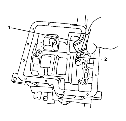
    Note: Close the other holes when blowing air using an air gun (1).

  16. Blow air into the oil inlet (2) of the control valve installation side, and check the functioning of the piston.


© Copyright Chevrolet. All rights reserved