Exhaust Gas Recirculation (EGR) System Description
The exhaust gas recirculation (EGR) system is used to reduce the amount of nitrogen oxide emission levels caused by combustion temperatures exceeding 816° C (1500° F). It does this by introducing small amounts of exhaust gas back into the combustion chamber. The exhaust gas absorbs a portion of the thermal energy produced by the combustion process and thus decreases combustion temperature. The EGR system will only operate under specific temperature, barometric pressure, and engine load conditions in order to prevent driveability concerns and to increase engine performance. The engine control module (ECM) calculates the amount of EGR needed based on the following inputs:
| • | The engine coolant temperature (ECT) sensor |
| • | The inlet air temperature (IAT) sensor |
| • | The barometric pressure (BARO) |
| • | The manifold absolute pressure (MAP) sensor |
| • | The throttle position sensor |
EGR Valve Circuits
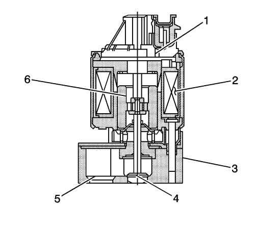
Linear EGR Valve
|
|---|
| (1) | Position Sensor |
| (2) | Coil Assembly |
| (3) | Base |
| (4) | Pintle |
| (5) | Exhaust In Port |
| (6) | Armature |
The exhaust gas recirculation (EGR) valve consists of the following circuits:
| • | An ignition circuit which supplies 12 V to the coil of the EGR valve |
| • | A control circuit which grounds the coil of the EGR valve. The control circuit is a pulse width modulated ground produced by an internal low side driver of the ECM. |
| • | A 5 V reference circuit supplied from the ECM to the internal position sensor of the EGR valve |
| • | A signal circuit which sends a feedback voltage from the internal position sensor of the EGR valve to the ECM. This voltage varies depending on the position of the EGR valve pintle. The ECM interprets this voltage as the position of the EGR valve pintle |
| • | A low reference circuit supplied from the ECM to the internal position sensor of the EGR valve |
EGR Diagnostics
The ECM tests the EGR flow during deceleration by momentarily commanding the EGR valve to open while monitoring the signal of the manifold absolute pressure (MAP) sensor. When the EGR valve is opened, the ECM will expect to see a predetermined increase in MAP. If the expected increase in MAP is not detected, the ECM records the amount of MAP difference that was detected and adjusts a calibrated fail counter towards a calibrated fail threshold level. When the fail counter exceeds the fail threshold level, the ECM will set a DTC.
The ECM monitors the position of the EGR valve pintle via the EGR position sensor. If the ECM detects a calibrated variance between the desired EGR valve pintle position and actual position for a calibrated amount of time, a DTC will set.
The ECM also monitors the circuits of the EGR valve for electrical faults. If a circuit fault is detected for a calibrated amount of time, a DTC will set.
| © Copyright Chevrolet. All rights reserved |


