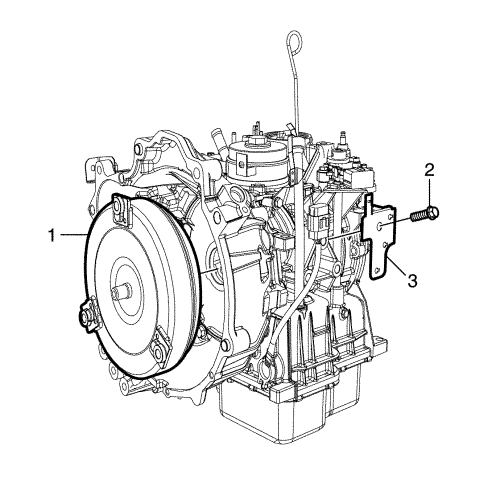
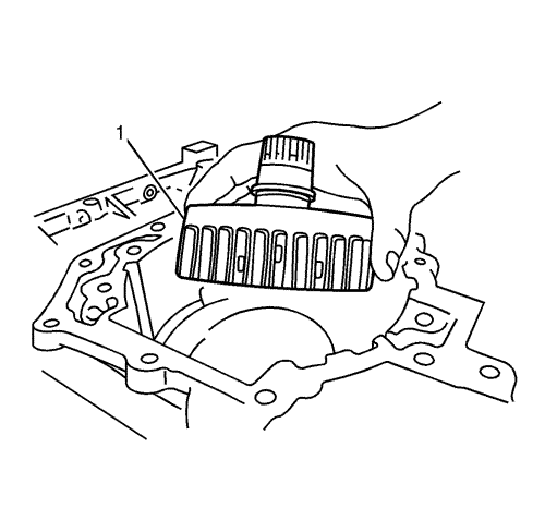
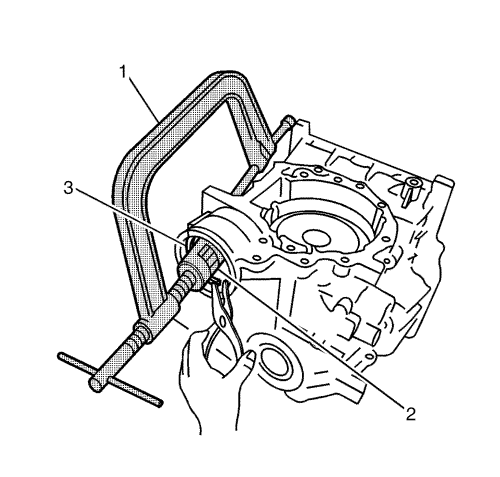
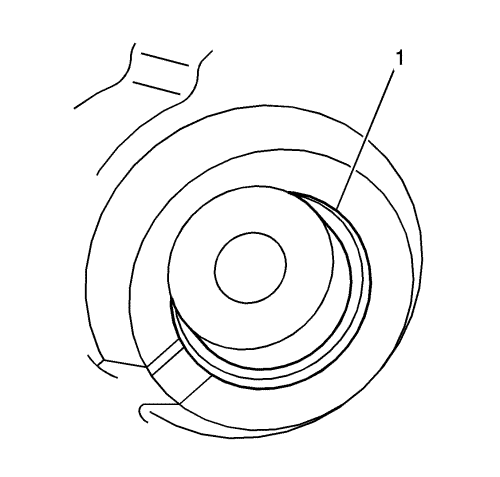
- Remove the torque converter (1).
- Remove the terminal connector bracket bolt (2) and the bracket (3).
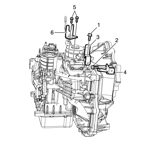
- Remove the bracket bolts (1, 2) and the brackets (3, 4).
- Remove the range selector lever cable bracket bolts (5).
- Remove the range selector lever cable bracket (6).
Note: Do not reuse O-ring.
- Remove the O-ring.
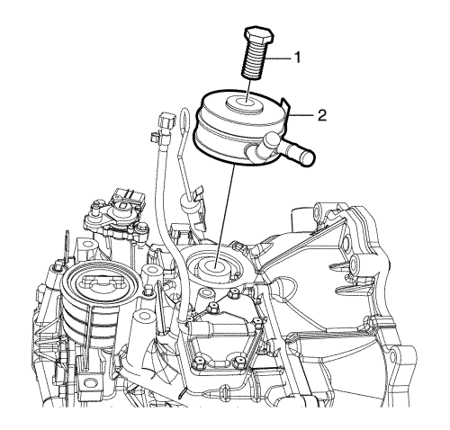
- Remove the oil cooler bolt (1).
- Remove the oil cooler (2).
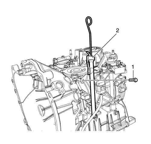
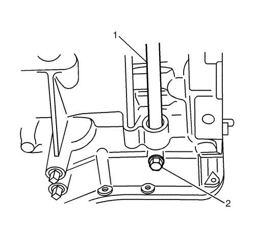
- Remove the oil filler tube bolt (1).
- Remove the oil filler tube (2).
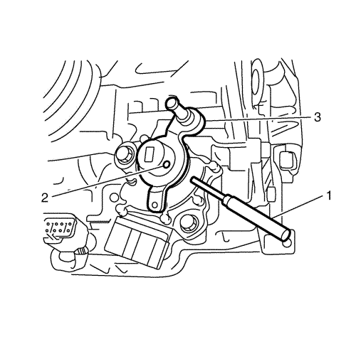
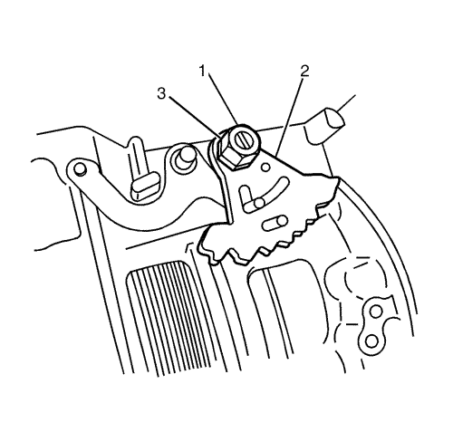
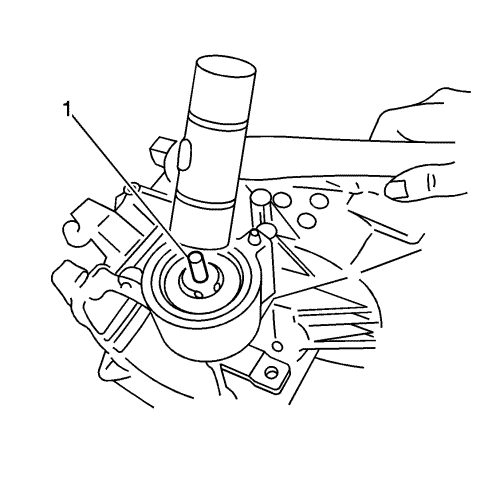
- Using the DT-50189 pin punch (1), remove the range selector lever pin (2) and the range selector lever (3).
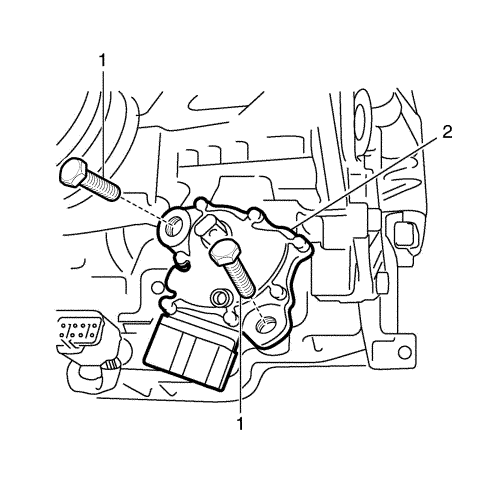
- Remove the park/neutral position (PNP) switch bolts (1).
- Remove the PNP switch (2).
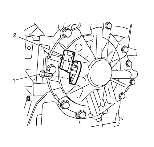
- Remove the input speed sensor bolt (1).
- Remove the input speed sensor (2).
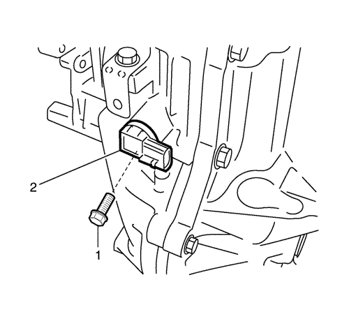
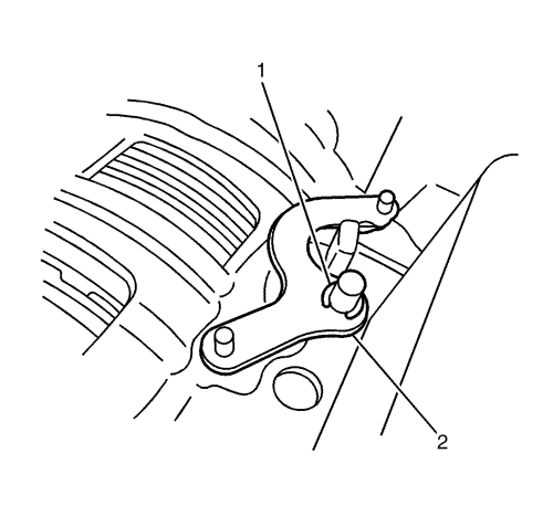
- Remove the output speed sensor bolt (1).
- Remove the output speed sensor (2).
Note:
| • | Remove any residual sealant from the housing and case surfaces. |
| • | Ensure that all sealant has been removed. |
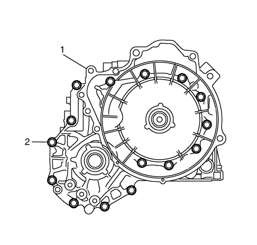
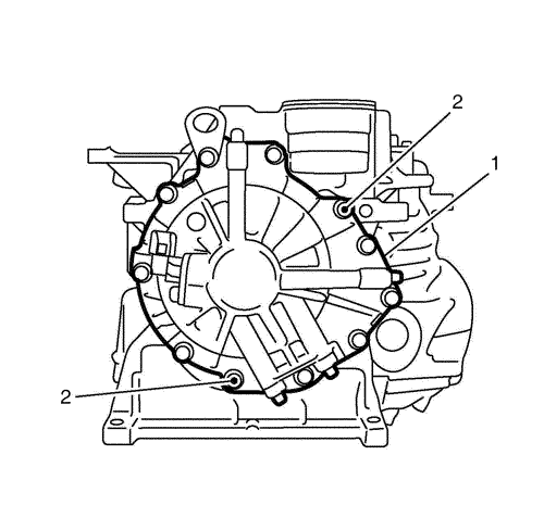
- With the converter housing (1) facing upward, remove the converter housing bolts (2). Then remove the converter housing, tapping it lightly with a plastic hammer.
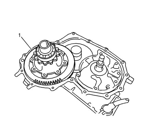
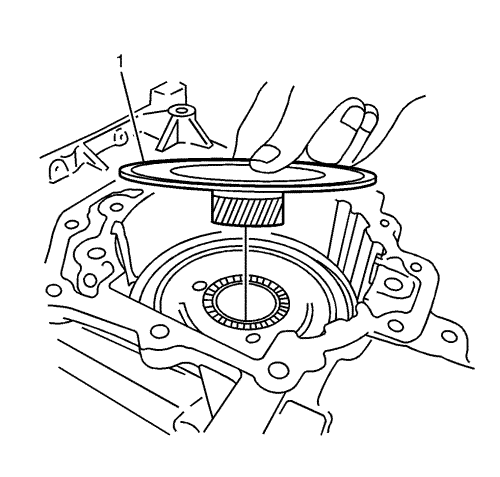
- Remove the differential assembly (1).
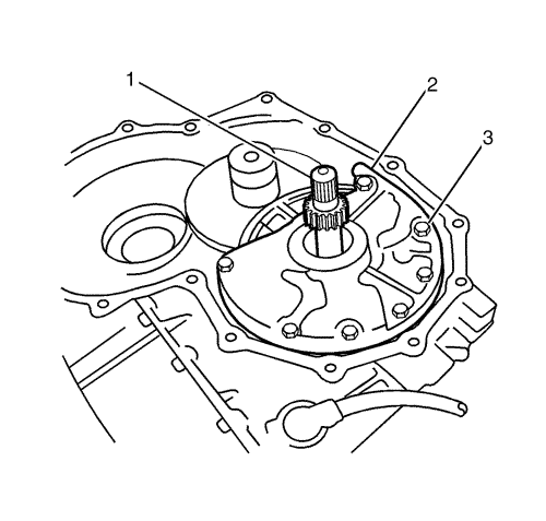
Note: When removing the oil pump, be careful not to drop the input shaft.
Note: For a transmission with lock-up function, be careful not to damage the O-ring between the input shaft and the torque converter.
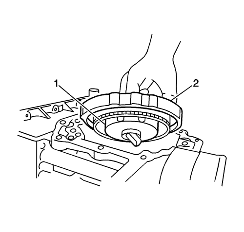
- Remove the input shaft O-ring (1), and then remove the oil pump bolts (3) and the oil pump (2).
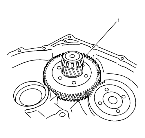
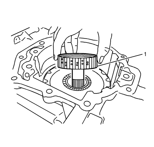
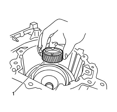
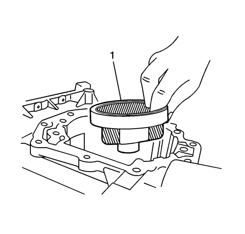
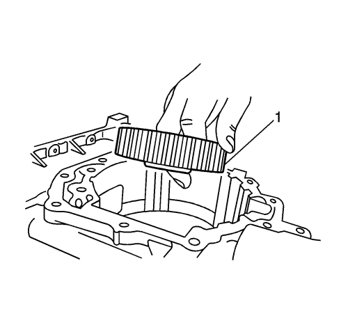
- Remove the reduction gear (1).
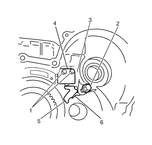
- Remove the support actuator bolts (1), the stopper bolt (2) and the support actuator (3).
- While wobbling the park pawl (4), pull out the park pawl shaft. Then, remove the park pawl, the park pawl spring (5) and the park pawl collar.
Note:
| • | Do not separate the stiffener from the oil sump with a screwdriver. |
| • | Remove any residual sealant from the pan and case surfaces. |
| • | Ensure that all sealant has been removed. |
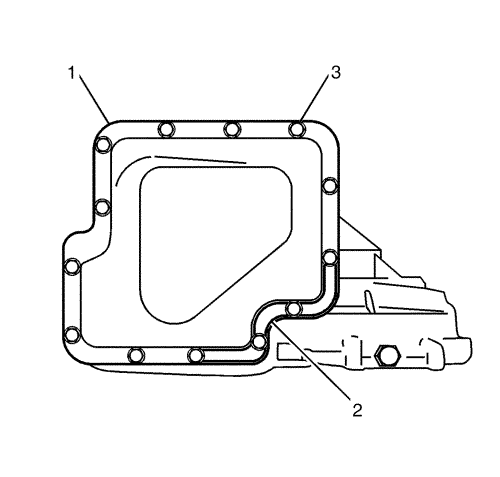
- Remove the oil sump bolts (3) with the oil sump (1) facing upward. Then, remove the stiffener (2) and the oil sump, tapping lightly with a plastic hammer.
- Remove the magnet from the oil sump.
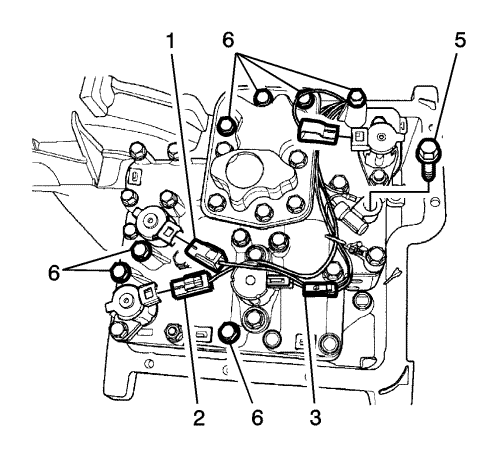
- Remove the connectors (1, 2, 3, 4) from each solenoid.
- Remove the bolt (5) which fixes the transmission fluid temperature sensor to the ground, and remove the 7 control valve body bolts (6). Then, remove the control valve body itself.
Note: Do not pull on the harness when removing the connector.
- While pushing the tabs (2), pull the solenoid connector (1) out from the case.
- Remove the 2 manual plate nuts (3) while holding the width across flats of the manual shaft (1), then remove the manual plate (2).
- Remove the manual shaft lock bolt (2), and pull out the manual shaft (1).
- Remove the E-ring (1), then remove the parking lever and the parking rod as the assembly (2).
Note:
| • | Remove the three O-rings from the end face of the case. |
| • | Do not separate the side cover from the transmission case with a screwdriver. |
| • | Remove any residual sealant from the surfaces of the side cover and transmission case completely. |
| • | Ensure that all sealant has been removed. |
- Remove the side cover bolts (2) with the cover facing upward, and then remove the side cover (1).
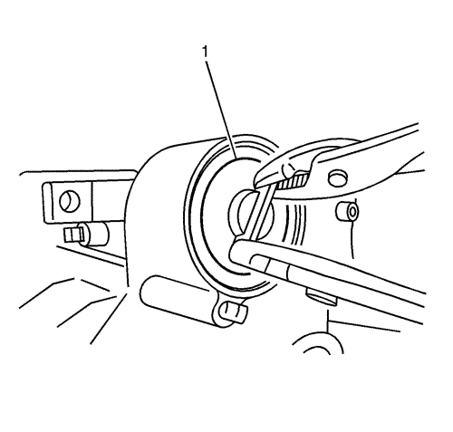
- Remove the circlip with a flat head screwdriver, and pull the band servo cover (1) out with a pair of pliers.
Note: Temporarily tighten the lock nut to prevent the air vent pin from coming out.
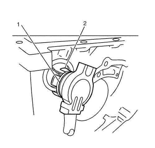
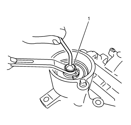
- Hold the piston stem (1), and loosen the lock nut.
- Loosen the piston stem.
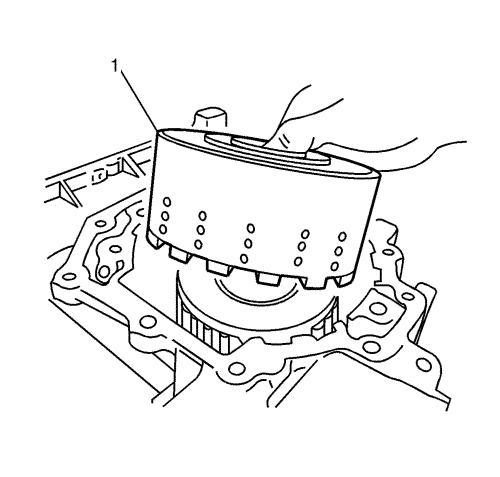
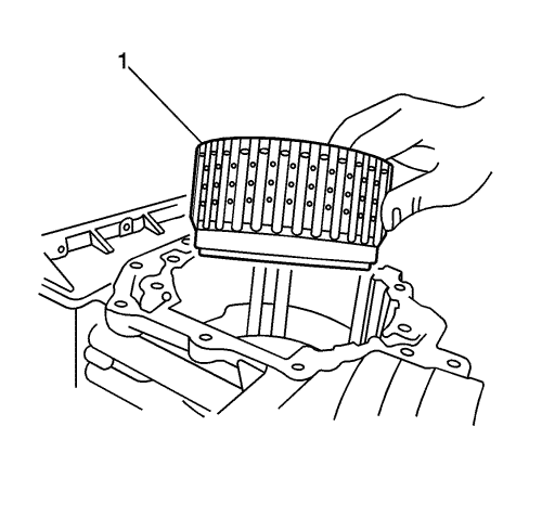
- Remove the reverse clutch drum (1).
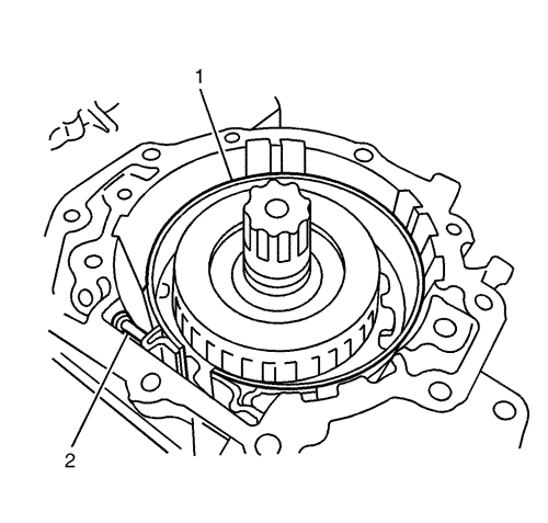
Note: To prevent cracking when expanding the brake band, bind it with wire.
- Remove the brake band (1).
- Remove the anchor end pin (2).
Note: Be careful not to drop the bearings from both sides of high clutch assembly.
- Remove the high clutch assembly (1).
- Remove the high clutch hub (1).
Note: Be careful not to drop bearings from the side cover side and the bearing race on the torque converter side of the front sun gear assembly.
- Remove the front sun gear assembly (1).
- Remove the circlip (3) from the band servo piston using DT-47523 valve lift (1) andDT-47522 valve lift attachment (2).
Note: The band servo piston may spring out because of the piston spring force. Be careful not to drop the piston.
- Lightly tap the piston stem (1) with a plastic hammer, and remove the band servo piston with the reaction force of the piston spring.
Note: Be careful not to drop the bearing from the side cover side and the race-combined bearing from the torque converter side of the front carrier.
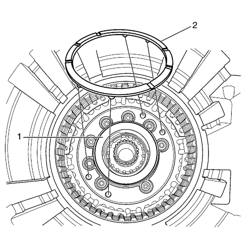
- Remove the circlip, then remove the front carrier (1) and the low one-way clutch (2) as an assembly.
- Remove the rear sun gear (1).
Note: Be careful not to drop the bearing from the side cover side and the race-combined bearing from the torque converter side of the rear carrier assembly.
- Remove the rear carrier assembly (1).
Note: Be careful not to drop the bearing from the side cover side and the race-combined bearing from the torque converter of the rear internal gear.
- Remove the rear internal gear (1).
Note: Be careful not to drop the race-combined bearings from the torque converter side of the low clutch assembly.
- Remove the low clutch assembly (1) as an assembly.
- Remove the bearing (1) and the thrust washer (2) from the output gear.
Note: Remove the seal ring before pulling the output gear assembly out. Do not reuse the seal ring.
- With the side cover installation upward, remove the 2 seal rings.
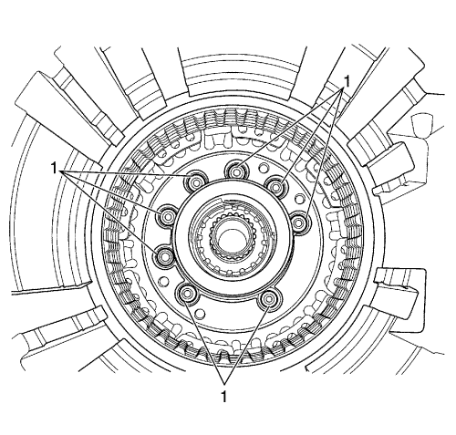
- Remove the 8 output gear bearing support installation bolts (1) with a hexagon wrench.
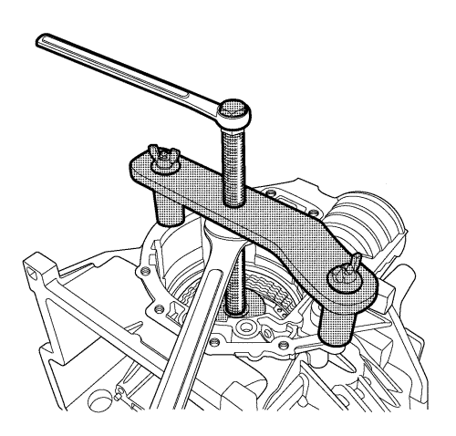
- Remove the output gear assembly using DT-50166 output gear assembly remover.
- Remove the front wheel drive shaft seal (1) of the case.
- Remove the input shaft oil seal from the converter housing.


