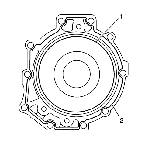
Note:
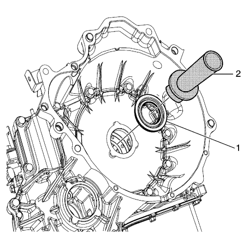
| • | Do not reuse the oil seal. |
| • | Apply grease to the lip of the oil seal. |
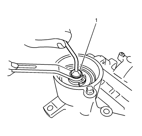
| • | The oil seal must be flush with the converter housing surface when installed. |
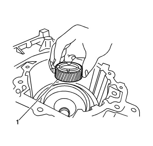
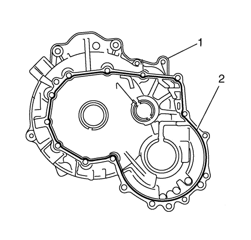
- Install the input shaft oil seal (1) into the converter housing using DT-47533 input shaft oil seal installer (2).
Note:
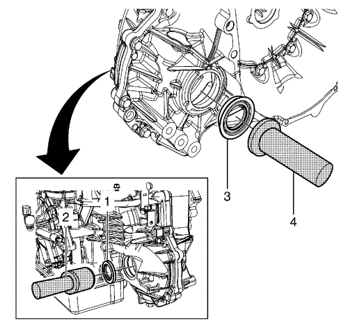
| • | Do not reuse the oil seal. |
| • | Apply grease to the lip of the oil seal. |
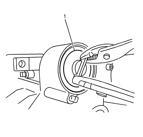
| • | Push the oil seal to the end. |
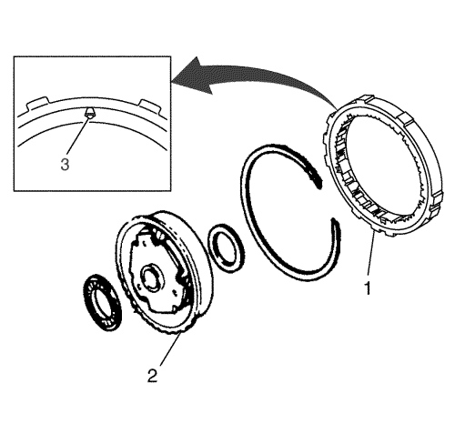
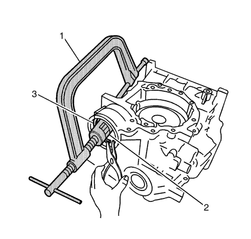
- Install the left front wheel drive shaft seal (1) and the right front wheel drive shaft seal (3) using DT-47535 seal installer (2) and DT-47534 seal installer (4).
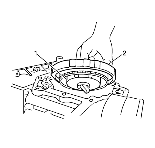
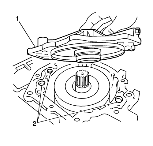
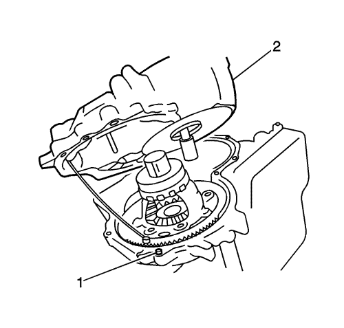
Note: Align the two oil inlets out of three oil inlets (3) on the oil sump side of the case with the oil inlet cut-out (1) of the output gear bearing support (2).
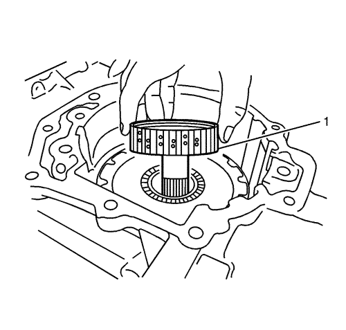
- Install the output gear assembly with converter housing facing upward.
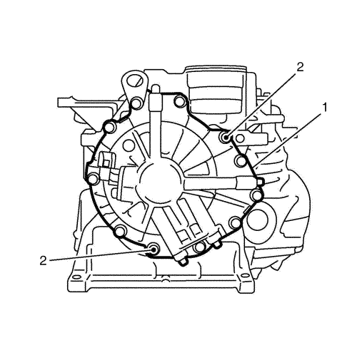
Caution: Refer to Fastener Caution in the Preface section.
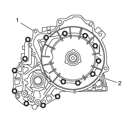
Note: Tighten the installation bolts diagonally and evenly.
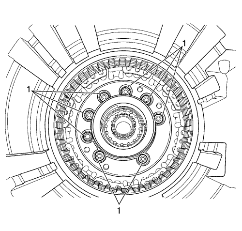
- With the side cover installation facing upward, install the output gear bearing support installation bolts (1) and tighten to 7 N·m (62 lb in).
Note: Apply ATF to the seal ring for easy installation of the low clutch.
- Install the 2 NEW seal rings.
- Install the bearing (1) and the thrust washer (2) to the output gear.
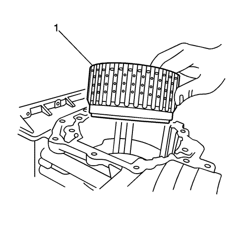
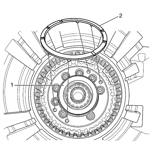
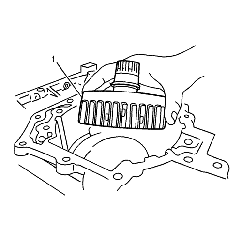
- Install the low clutch assembly (1) so that it is engaged with the low and reverse brake plates.
Note:
| • | When installing the internal gear, be careful not to catch the Teflon ring of the case side inner race. |
| • | Be sure to install at the bottom of the low clutch. |
| • | Be careful not to drop the bearing. |
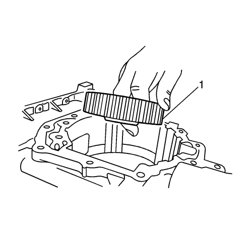
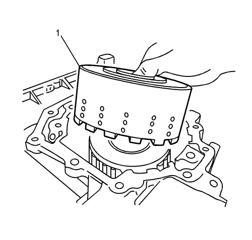
- Attach the bearing to the side cover side and the race-combined bearing to the torque converter side of the rear internal gear (1) with petroleum jelly, and install the rear internal gear so that it is engaged with the low clutch plates.
Note: Be careful not to drop the bearing race.
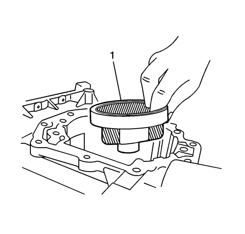
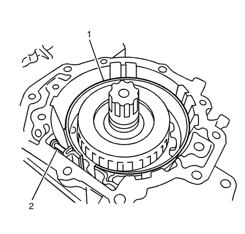
- Attach the bearing to the side cover side and the race to the engine side of the rear carrier assembly (1) with petroleum jelly, and install the rear carrier assembly so that it is engaged with the internal gear.
Note: Note the direction of the rear sun gear.
- Install the rear sun gear (1) to the rear carrier assembly with the polished face downward.
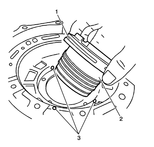
Note: After installation, ensure that the clutch rotates clockwise smoothly and locks in the anticlockwise direction.
- Install the low one-way clutch (1) to the front carrier (2), facing the clinches (3) of the side plate toward the torque converter.
Note: Ensure that the front carrier periphery spline is engaged with that of the low clutch. Ensure that the low one-way clutch is flush with the top of the front carrier.
- Attach the bearings to the side cover side and the race-combined bearing to the torque converter side of the front carrier (1) with petroleum jelly, then install the front carrier (1) and the low one-way clutch (2) as an assembly, following the guide of the case.
- Install the snap ring.
- Attach the bearing to the side cover side and the race to the torque converter side of the front sun gear assembly (1) with petroleum jelly, and install the assembly in the front carrier.
Note: The bearing to be installed in the hub is small in diameter. Be sure to position in the centre.
- Attach the bearing to the side cover side of the high clutch hub (1) with petroleum jelly, and install the high clutch hub (1) in the front sun gear assembly.
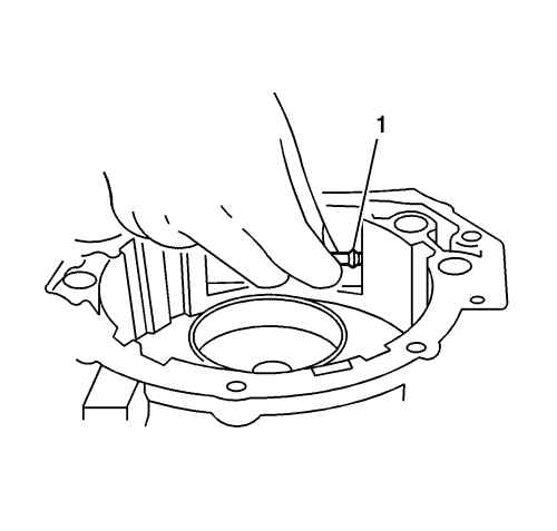
- Install the brake band anchor end pin (1) in the case.
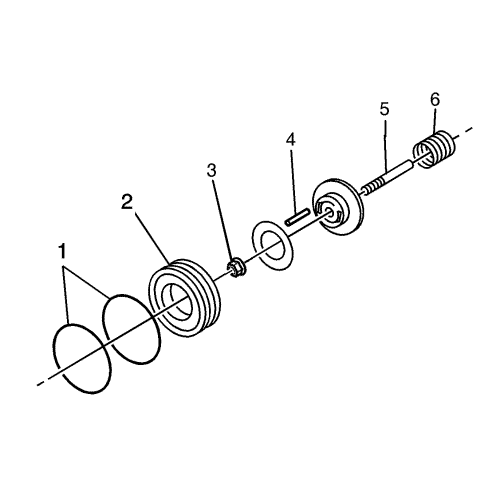
- Apply ATF to the new O-ring (1) then install them to the band servo piston (2).
- Secure the spring (6) to the centre of the piston with petroleum jelly.
- Gently tighten the anchor end nut (3) of the band servo stem shaft (5) so that the air vent pin (4) does not drop.
Note: Be sure to take this step to prevent O-ring breakage.
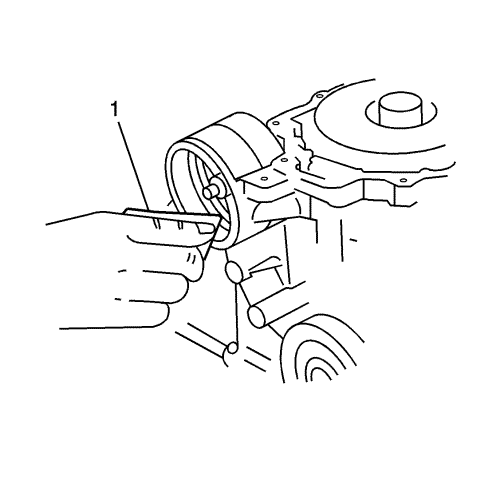
- Before installing the band servo cover, remove any scratches from the case surface with sandpaper (1).
- Insert the band servo piston into the case and push it into the circlip groove using DT-47523 tappet (1) and DT-47522 tappet attachment (2) then fasten the circlip (3).
- Attach the bearing to the side cover side of the high clutch assembly (1) with petroleum jelly, and install the high clutch assembly so that it is engaged to the high clutch hub.
- Install the reverse clutch drum (1) so that it is engaged to the high clutch hub.
- Through the anchor end pin (2) and the piston, install the brake band (1) level with the reverse clutch. Gently tighten the piston.
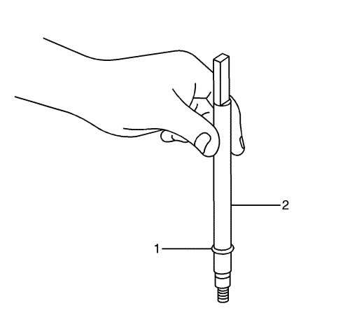
- Loosen the anchor end nut as much as possible. Tighten the band servo stem to 3 N·m (27 lb in) , then loosen it back by 2.5 turns from that position. Tighten the anchor end nut to 33 N·m (24 lb ft) while holding the piston stem (1).
Note: Before installation, apply ATF to the O-ring.
- Insert the band servo cover (1) horizontally.
Note: Be sure that the circlip is entirely in the groove.
- Install the snap ring.
- Measure the side cover end play and select a suitable thrust washer.
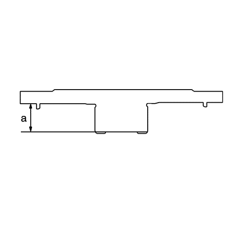
- Measure dimension a from the case installation surface of the side cover to the sealing surface of the race bearing.
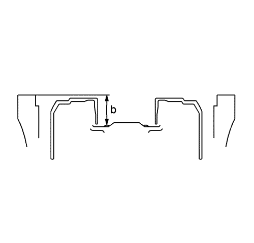
- Measure dimension b from the side cover installation surface of the case to the top of the high clutch bearing.
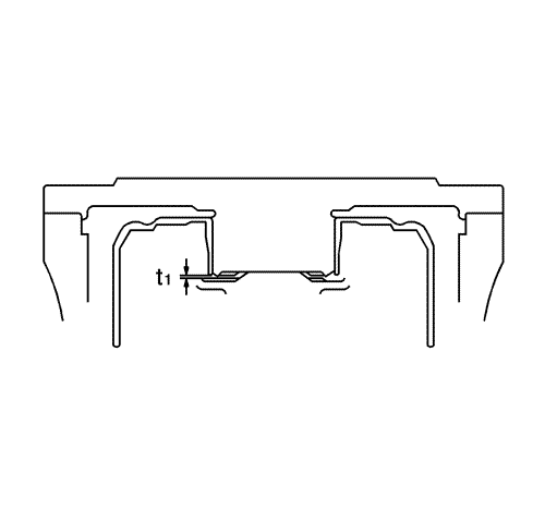
Note: If Dimension t1 is not within the specified clearance, replace the selected high clutch bearing with another one and calculate the clearance again. Then, select a race.
- Calculate the clearance using the formula Dimension b minus Dimension a, and select a suitable race so that Dimension t1 will be the specified clearance.
Clearance
t1 specified clearance is 0.25--0.55 mm (0.010--0.02 in)
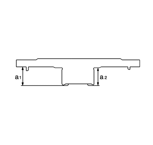
- Measure the Dimensions a1 and a2 of the side cover.
- Calculate the Dimension a by the formula a2-a1.
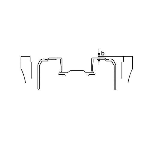
- Measure Dimension b from the side cover installation surface of the case to the washer seating surface of the reverse clutch.
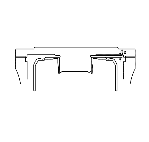
- Calculate the clearance using the formula Dimension b minus Dimension a, and select a suitable thrust washer so that Dimension t2 will be the specified clearance.
Clearance
t2 specified clearance is 0.55--0.90 mm (0.02--0.03 in).
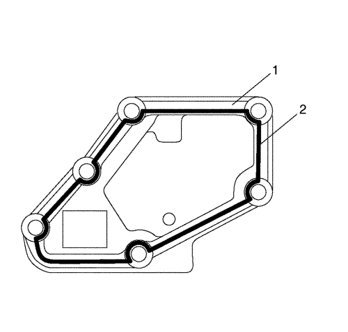
Note:
| • | The coat of sealant should be wide and thick, approximately 2 mm (0.08 in) in width and 1 mm (0.04 in) thick. |
| • | The sealant should be applied thoroughly and evenly. |
- Apply sealant (2) to the side cover (1) as shown.
Note: Do not reuse the O-rings. Apply ATF to the new O-rings before the installation of the side cover (1).
- Position the three O-rings (2) in the case.
Note:
| • | Be careful not to damage the Teflon rings attached to the high clutch and the side cover. |
| • | Two of the side cover bolts (2) securing the side cover are a bolt with sealant. |
| • | Ensure that the race is positioned onto the groove for the bottom of the side cover. |
| • | Be sure to replace the side cover bolt with a new one and install it in the correct position. |
- Install the side cover (1) in the case.
- Install the side cover bolts and tighten to 21 N·m (15 lb ft).
- Install the parking rod (2) and the parking lever as an assembly in the case, and install the E-ring (1).
- Install the O-ring (1) in the manual shaft, and insert the manual shaft (2) from inside the case.
Note: Do not reuse the lock bolt as sealant may be attached to it.
- Install the manual shaft lock bolt (2) to secure the manual shaft (1) and tighten to 7 N·m (62 lb in).
- Install the manual plate (2) in the manual shaft (1).
- Fix the manual shaft outside the transmission case.
- Install the 2 manual plate nuts (3) and tighten to 13 N·m (115 lb in).
- Install the solenoid connector (1) in the case.
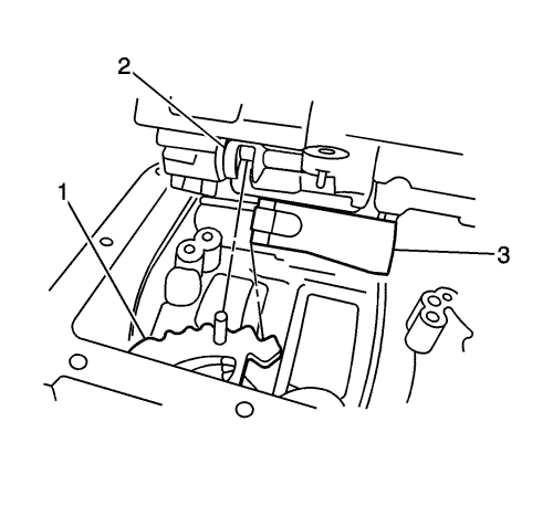
Note:
| • | Ensure that the valve is fixed to the location pin. |
| • | After installing the valve, ensure again with your fingers that the manual valve is engaged with the manual plate pin. |
- While hanging the detent spring (3) on the manual plate (1), engage the manual valve (2) with the manual plate pin, and install the control valve body.
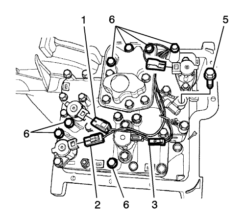
- Install the 7 control valve body bolts (6) and tighten to 8 N·m (71 lb in).
- Install the TFT sensor, the bolt (5) and the ground terminal together.
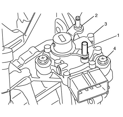
- Connect the 1-2 shift solenoid valve electrical connector (green) (1), 2-3 shift solenoid valve electrical connector (white) (2), pressure control solenoid valve electrical connector (brown) (3) and torque converter clutch solenoid valve electrical connector (black) (4).
- Install the magnet in the oil sump (1).
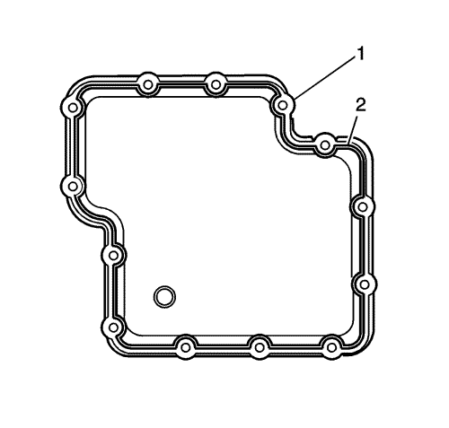
Note:
| • | The coat of sealant should be wide and thick, approximately 3 mm (0.12 in) in width and 1.5 mm (0.06 in) thick. |
| • | The sealant should be applied thoroughly and evenly. |
- Apply sealant (2) to the oil sump (1).
Note: The 4 bolts which secure the stiffener are of different lengths. Be sure to position them in the right places.
- While fixing the stiffener (2) to the 4 oil sump bolts, install the oil sump bolts (3) into the oil sump (1) and tighten to 13 N·m (115 lb in).
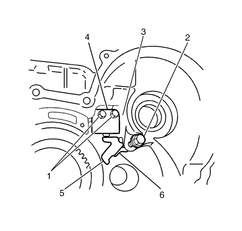
- Position the park pawl (4), the park pawl spring (5) and the parking pawl collar in the hole, and secure them by inserting the park pawl shaft.
- Install the support actuator (3).
- Install the support actuator bolts (1) and tighten to 27 N·m (20 lb ft).
- Install the stopper bolt (2) of the parking pawl shaft and tighten to 5 N·m (44 lb in).
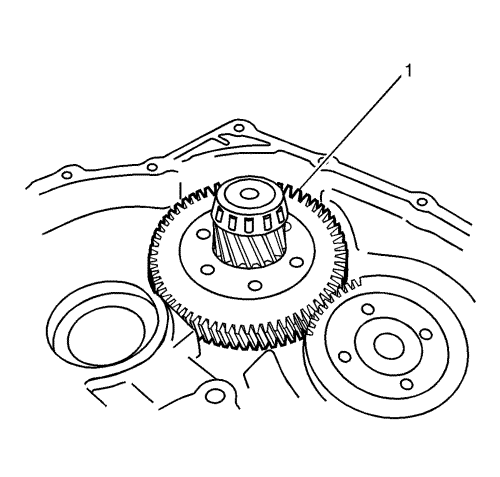
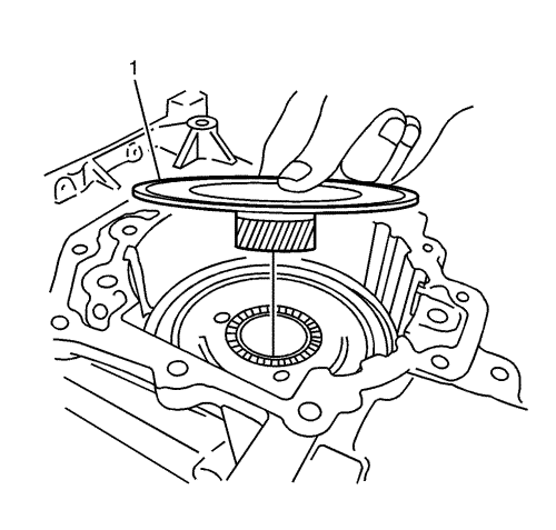
- Install the reduction gear (1) with the converter housing facing upward.
Note:
| • | Do not reuse the input shaft seal ring. Apply ATF to a new seal ring before installation. |
| • | Do not reuse O-ring. Apply ATF to the new O-ring before installation. |
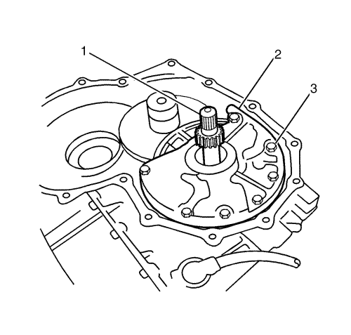
- Insert the input shaft in the centre of the output gear.
- Install the oil pump (2).
- Install the oil pump bolts (3) and tighten to 13 N·m (115 lb in).
- Install the input shaft O-ring (1) in the input shaft.
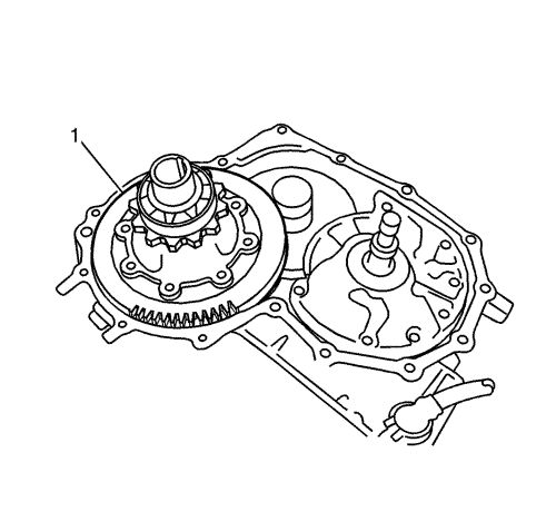
Note: Ensure that the differential assembly is flush with the reduction gear.
- Install the differential assembly (1) so that it is engaged with the reduction gear.
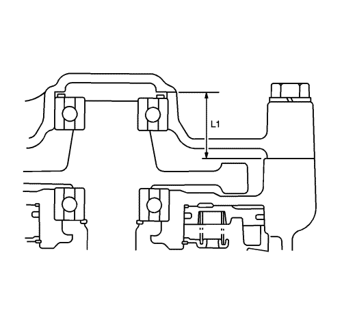
- Select a differential assembly shim.
- Measure dimension L1 from the case installation surface of the converter housing to the seating surface of the shim bearing.
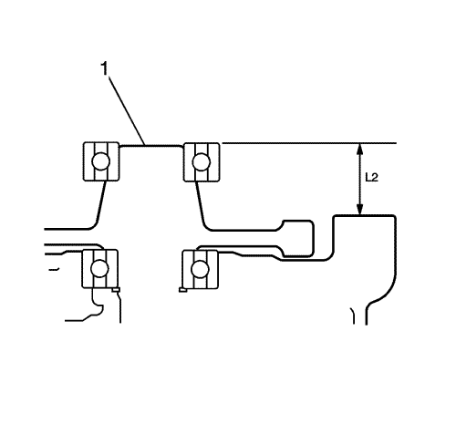
- Measure dimension L2 from the converter housing installation surface of the case to the top of the differential assembly (1) side bearing.
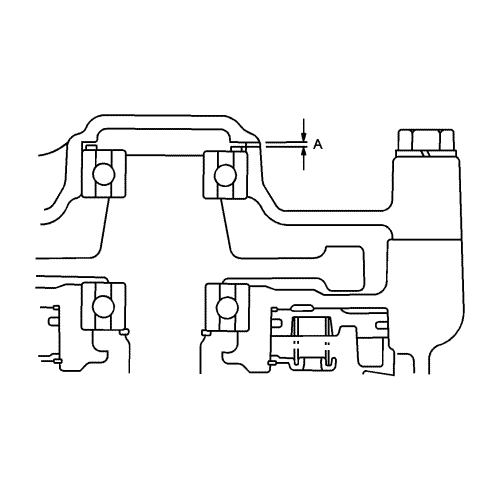
- Calculate the clearance by the formula dimension L1 minus dimension L2 and select a suitable shim so that dimension A will be the specified clearance.
Clearance
The specification clearance is A: 0--0.1 mm (0--0.004 in)
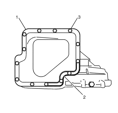
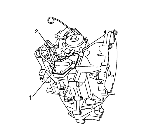
Note:
| • | The coat of sealant should be wide and thick, approximately 2 mm (0.08 in) in width and 1 mm (0.04 in) thick. |
| • | The sealant should be applied thoroughly and evenly. |
- Apply sealant (2) to the converter housing (1).
- Install the converter housing (2) aligning with the case alignment pin (1).
Note:
| • | One of the bolts securing the converter housing (1) is a bolt with sealant (2). |
| • | Be sure to replace the bolt with a new one and install it in the correct position. |
- Install the converter housing bolts (2) and tighten to 30 N·m (22 lb ft).
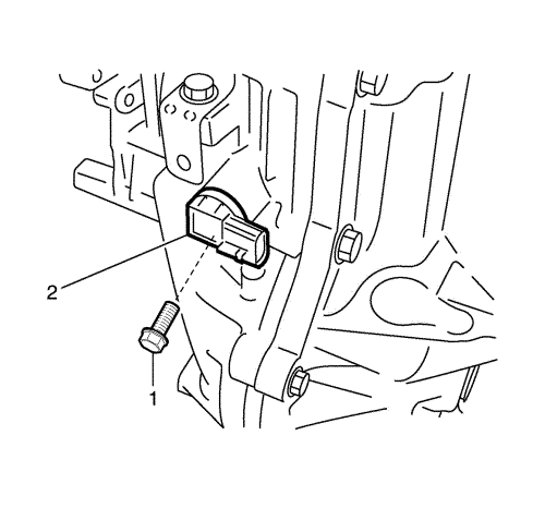
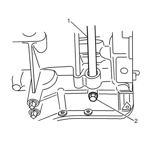
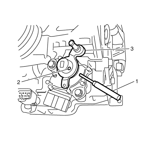
- Install the output speed sensor (2).
- Install the output speed sensor bolt (1) and tighten to 7 N·m (62 lb in).
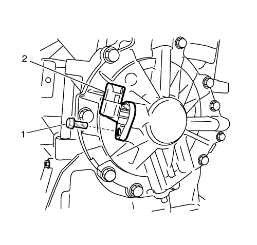
- Install the input speed sensor (2).
- Install the input speed sensor bolt (1) and tighten to 6 N·m (53 lb in).
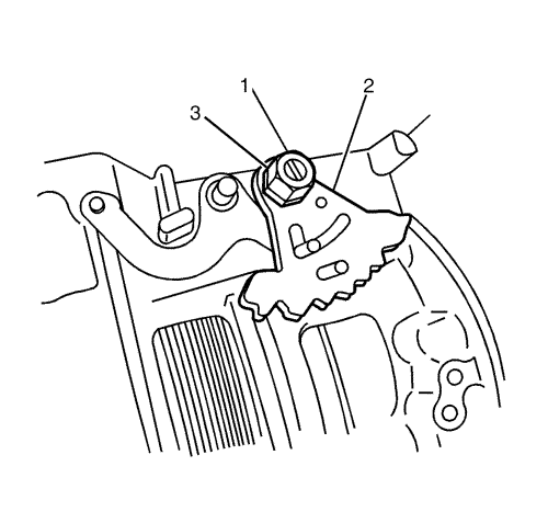
- Install the park/neutral position (PNP) switch through the manual shaft, and temporarily tighten the bolts.
- Embed the range selector lever (3) in the manual shaft, and install the range selector lever pin (2).
- Move the range selector lever (2) to shift into N (Neutral) range.
- Insert a 3 mm (0.11 in) pin (drill bit) (1) in the location holes of the PNP switch (3) and the range selector lever.
- Install the PNP switch bolts (4) and tighten to 3 N·m (27 lb in).
Note:
| • | Do not remove the air breather cover when usually inside transmission is disassembled. |
| • | The air breather cover can be applied a sealant, and bolting of a bolt in this procedure, only in case of that is required replacement by any damaged. |
| • | The coat of sealant should be approximately 1.6 mm (0.06 in) in width and 1 mm (0.04 in) thick. |
| • | The sealant should be applied thoroughly and evenly. |
- Apply sealant (2) to the air breather cover (1).
- Install the air breather cover (1) in the case.
- Install the air breather cover bolts (2) and tighten to 12 N·m (106 lb in).
Note:
| • | Before installation, attach the O-ring to the oil cooler with petroleum jelly. |
| • | Do not reuse the O-ring. |
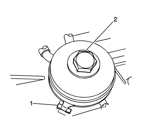
- Align the convex section of the oil cooler with the case cut-out (1).
- Install the oil cooler bolt (2) and tighten to 35 N·m (26 lb ft).
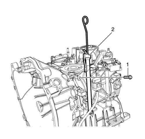
- Install the oil filler tube (2) in the case and fix it to the case together with solenoid connector.
- Install the oil filler tube bolt (1) and tighten to 7 N·m (62 lb in).
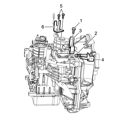
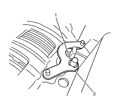
- Install the transmission case side bracket (3), the bracket bolt (1) and tighten to 13 N·m (115 lb in).
- Install the converter housing side bracket (4), the bracket bolt (2) and tighten to 44 N·m (33 lb ft).
- Install the range selector lever cable bracket (6).
- Install the range selector lever cable bracket bolts (5) and tighten to 19 N·m (14 lb ft).
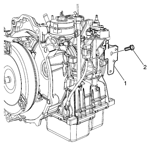
- Install the terminal connector bracket (1), the bracket bolt (2) and tighten to 44 N·m (33 lb ft).
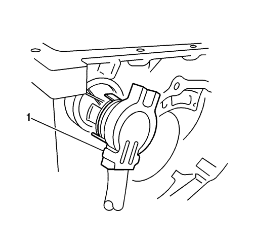
Note: Pour ATF to the extent that the ATF does not spill when setting up the torque converter (1).
- Install the torque converter (1), turning it until the converter sleeve cut-out is aligned with the input shaft.
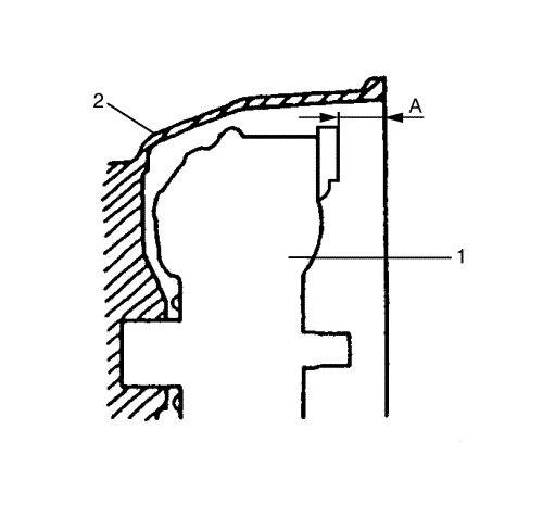
- Measure dimension A from the edge of the converter to the edge of the case to ensure that the converter is installed properly.
Dimension
The dimension A is 23.7 mm or more (0.9 in or more).
- Install the torque converter (1).


