Spark |
||||||||
|
|
|
|||||||
Note: DO NOT use a wire brush any part of the piston.
Warning: Refer to Safety Glasses and Compressed Air Warning in the Preface section.
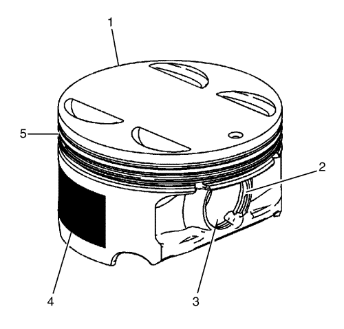
| • | Ring grooves for nicks, burrs that may cause binding (5) |
| • | Warped or worn ring lands (5) |
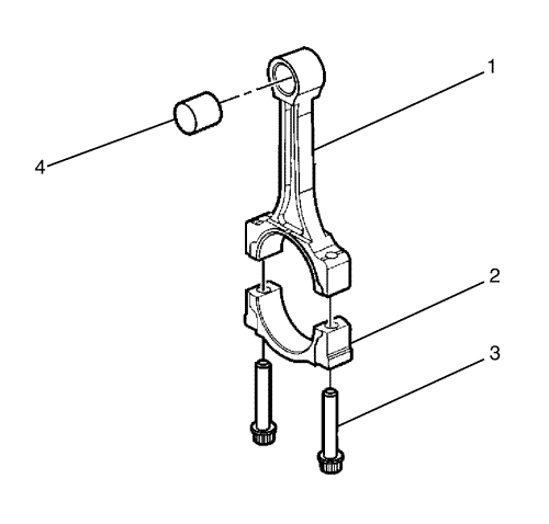
| • | Piston pin retainer grooves for burrs (2) |
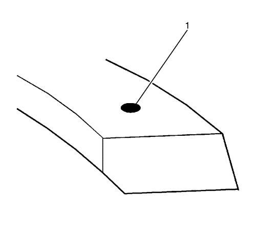
| • | Eroded areas at the top of the piston (1) |
| • | Scuffed or damaged skirt coating (4) |
| • | Worn piston pin bores or worn piston pins (3) |
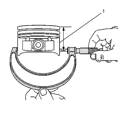
| 1.1. | Using an outside micrometer, measure the width of the piston at 30 mm (1.181 in) below the crown, top (1), at the thrust surfaces of the piston, perpendicular to the piston pin centreline. |
| 1.2. | Compare your results with the engine mechanical specifications. Refer to Engine Mechanical Specifications |
| 1.3. | If the clearance obtained through measurement is greater than the provided specifications and the cylinder bores are within specification, replace the piston. |
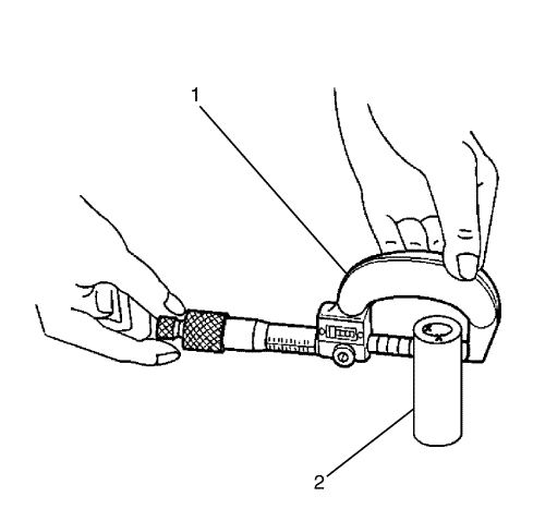
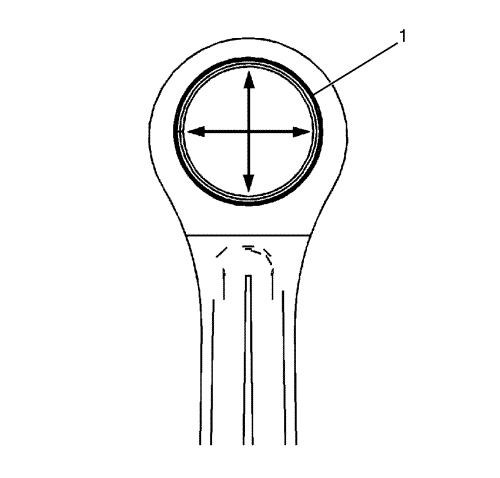
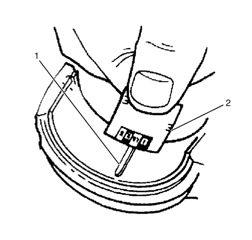
| 2.1. | Piston pin bores and pins must be free of varnish or scuffing. |
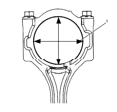
| 2.2. | Use an outside micrometer (1) to measure the gudgeon pin in the piston contact areas. |
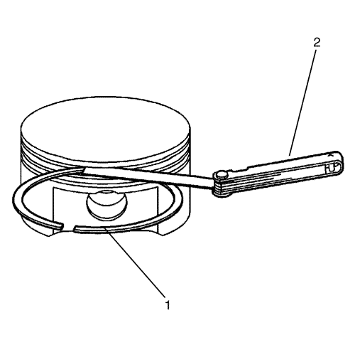
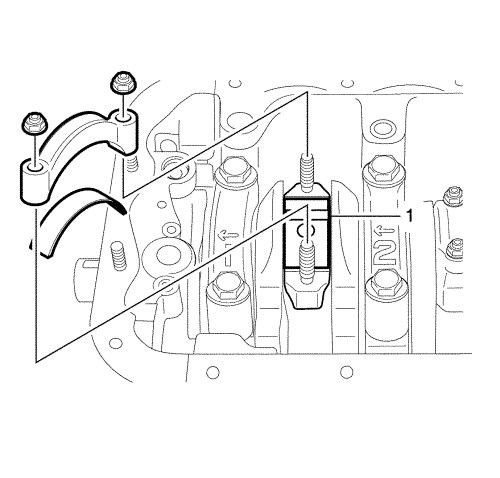
| 1.1. | Roll the piston ring (1) entirely around the piston ring groove. If any binding is caused by the ring groove, dress the groove with a fine file. If any binding is caused by a distorted piston ring (1), replace the piston ring (1). |
| 1.2. | With the piston ring (1) on the piston, use feeler gauges (2) to check clearance at multiple locations. |
| 1.3. | Compare the measurements with piston ring side clearance listed in the. |
| 1.4. | If the clearance is greater than specifications, replace the piston ring (1). |
Warning: Refer to Safety Glasses and Compressed Air Warning in the Preface section.
Note: DO NOT scrape the rod or rod cap.
Caution: Refer to Fastener Caution in the Preface section.
| © Copyright Chevrolet. All rights reserved |


