To the top of the document
Spark
   
GMDE Start Page Load static TOC Load dynamic TOC Help?

Body Lock Pillar Outer Panel Reinforcement Replacement

Removal Procedure

    Warning: Refer to Approved Equipment for Collision Repair Warning in the Preface section.

    Warning: Refer to Glass and Sheet Metal Handling Warning in the Preface section.

  1. Disable the SIR system. Refer to SIR Disabling and Enabling .
  2. Disconnect the negative battery cable. Refer to Battery Negative Cable Disconnection and Connection .
  3. Remove all related panels and components.
  4. Visually inspect the damage. Repair as much of the damage as possible.
  5. Remove the sealers and anti-corrosion materials from the repair area, as necessary. Refer to Anti-Corrosion Treatment and Repair .

  6. 2327450
  7. Locate and mark all the necessary factory welds of the body lock pillar outer panel reinforcement.
  8. Drill all factory welds. Note the number and location of welds for installation of the service assembly.

  9. 2327430
  10. Remove the damaged body lock pillar outer panel reinforcement.

Installation Procedure

  1. Prepare all mating surfaces as necessary.
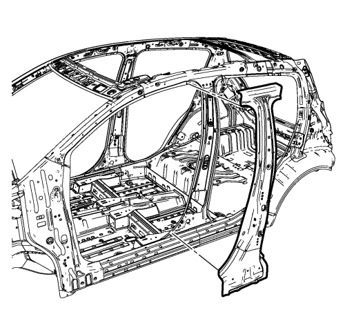
  2. Align the body lock pillar outer panel reinforcement.

  3. 2327427
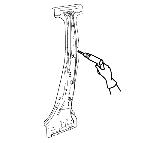
  4. Drill a 8 mm (5/16 in) for plug welding along the edges of the body lock pillar outer panel reinforcement as noted from the original panel.
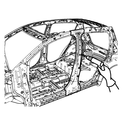
  5. Clean and prepare the attaching surfaces for welding.
  6. Position the body lock pillar outer panel reinforcement on the vehicle.
  7. Verify the fit of the body lock pillar outer panel reinforcement.
  8. Clamp the body lock pillar outer panel reinforcement into position.

  9. 2327425
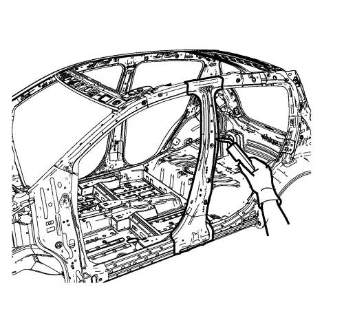
  10. Plug the weld accordingly.
  11. To create a solid weld with minimum heat distortion, make 25 mm (1 in) stitch welds along the seam with 25 mm (1 in) gaps between them. Then go back and complete the stitch weld.
  12. Apply the sealers and anti-corrosion materials to the repair area, as necessary. Refer to Anti-Corrosion Treatment and Repair .
  13. Paint the repaired area. Refer to Basecoat/Clearcoat Paint Systems .
  14. Install all related panels and components.
  15. Connect the negative battery cable. Refer to Battery Negative Cable Disconnection and Connection .
  16. Enable the SIR system. Refer to SIR Disabling and Enabling .


© Copyright Chevrolet. All rights reserved