Master Cylinder Replacement — Right Hand Drive
Removal Procedure
Warning: Refer to Brake Fluid Irritant Warning in the Preface section.
Caution: Refer to Brake Fluid Effects on Paint and Electrical Components Caution in the Preface section.
- Place the ignition switch in the OFF position.
- Remove the radiator surge tank to gain easy tool access. Refer to Radiator Surge Tank Replacement .
- Apply and release the brake pedal several times until the pedal becomes firm to deplete the power vacuum brake booster vacuum reserve.
- Thoroughly clean the master cylinder reservoir and the master cylinder body to remove any dirt and debris.
- Disconnect the brake fluid level indicator switch electrical connector.
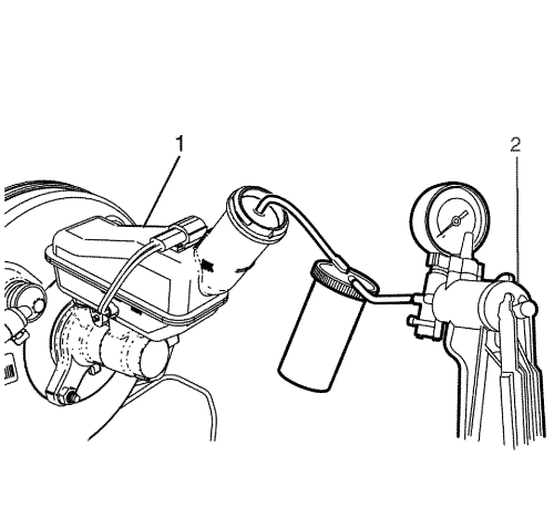
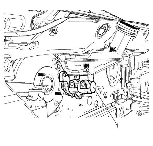
- Syphon the brake fluid out of the master cylinder reservoir (1) using an air vacuum pump or a hand vacuum pump (2).
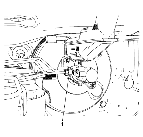
- Disconnect the master cylinder secondary brake pipe fitting (1).
Cap the brake pipe fitting and plug the master cylinder outlet port to prevent brake fluid loss and contamination.
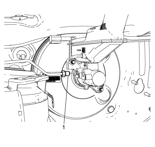
- Disconnect the master cylinder primary brake pipe fitting (1).
Cap the brake pipe fitting and plug the master cylinder outlet port to prevent brake fluid loss and contamination.
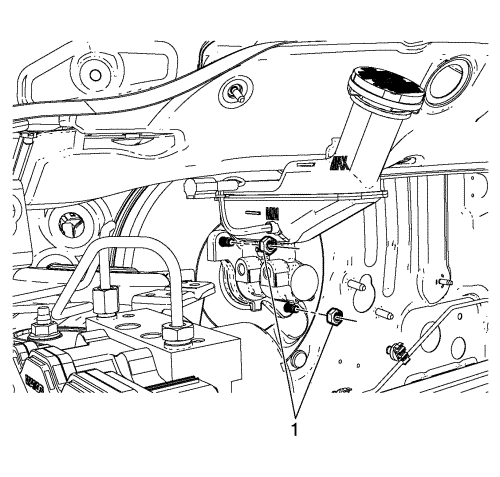
- Remove the master cylinder nuts (1).
- Remove the master cylinder (1) from the power vacuum brake booster.
- Remove the brake fluid level indicator switch, if necessary. Refer to Brake Fluid Level Indicator Switch Replacement .
- Remove the master cylinder reservoir, if necessary. Refer to Master Cylinder Reservoir Replacement .
Installation Procedure
- Install the master cylinder reservoir, if removed. Refer to Master Cylinder Reservoir Replacement .
- Bench bleed the master cylinder. Refer to Master Cylinder Bench Bleeding .
- Install the brake fluid level indicator switch, if removed. Refer to Brake Fluid Level Indicator Switch Replacement .
- Install the master cylinder (1) to the power vacuum brake booster.
Caution: Refer to Fastener Caution in the Preface section.
- Install the master cylinder nuts (1) and tighten the nuts to 13 N·m (115 lb in).
- Connect the master cylinder primary brake pipe fitting (1) and tighten to 18 N·m (13 lb in).
- Connect the master cylinder secondary brake pipe fitting (1) and tighten to 18 N·m (13 lb in).
- Connect the brake fluid level indicator switch electrical connector.
- Install the radiator surge tank. Refer to Radiator Surge Tank Replacement .
- Bleed the hydraulic brake system. Refer to
Hydraulic Brake System Bleeding : Pressure → Manual .
| © Copyright Chevrolet. All rights reserved |


