Throttle Actuator Control (TAC) System Description
The throttle actuator control (TAC) system is used to improve emissions, fuel economy, and driveability. The TAC system eliminates the mechanical link between the accelerator pedal and the throttle plate. The TAC system eliminates the need for a cruise control module and idle air control motor. The following is a list of TAC system components:
| • | The accelerator pedal assembly includes the following components: |
| - | The accelerator pedal position (APP) sensor 1 |
| • | The throttle body assembly includes the following components: |
| - | The throttle position sensor 1 |
| - | The throttle position sensor 2 |
| - | The throttle actuator motor |
| • | The engine control module (ECM) |
The ECM monitors the driver demand for acceleration with 2 APP sensors. The APP sensor 1 signal voltage range is from about 0.5-4.5V as the accelerator pedal is moved from the rest pedal position to the full pedal travel position. The APP sensor 2 range is from about 0.3-2.2V as the accelerator pedal is moved from the rest pedal position to the full pedal travel position. The ECM processes this information along with other sensor inputs to command the throttle plate to a certain position.
The throttle plate is controlled with a direct current motor called a throttle actuator control motor. The ECM can move this motor in the forward or reverse direction by controlling battery voltage and/or ground to 2 internal drivers. The throttle plate is held at a 5.7 degree rest position or the un-powered position using a constant force return spring. This spring holds the throttle plate to the rest position when there is no current flowing to the actuator motor.
The ECM monitors the throttle plate angle with 2 throttle position sensors. The throttle position sensor 1 signal voltage range is from about 0.95-4.35V as the throttle plate is moved from idle to wide open throttle (WOT) position. The throttle position sensor 2 voltage range is from about 4.05-0.65 V as the throttle plate is moved from idle to WOT position.
The ECM performs diagnostics that monitor the voltage levels of both APP sensors, both throttle position sensors, and the TAC motor circuit. It also monitors the spring return rate of the return springs that are housed internal to the throttle body assembly. These diagnostics are performed at different times based on whether the engine is running, not running, or whether the ECM is currently in a throttle body relearn procedure.
Every time the ignition cycle is cycled OFF, the ECM performs a quick throttle return spring test to make sure the throttle plate can return to the 7% rest position from the 0% position. This is to ensure that the throttle plate can be brought to the rest position in case of an actuator motor circuit failure. Observe, under cold conditions, the ECM commands the throttle plate to 0% with the ignition ON and the engine OFF to release any ice that may have formed on the throttle plate.
Throttle Body Relearn Procedure
The engine control module (ECM) stores values that include the lowest possible throttle position sensor positions and the rest positions. These values will only be erased or overwritten if the ECM is reprogrammed or if a throttle body relearn procedure is performed. Observe, if the battery is disconnected, the ECM will immediately perform a throttle body relearn procedure when the ignition is turned ON.
The ECM performs a relearn procedure twice and compares the results. If the results are nearly the same, the values are stored and the learn procedure is complete. The following is when the ECM performs a learn procedure:
| • | The engine is cranking. |
| • | The ignition is cycled OFF. |
The ECM performs the learn procedure every 15 ignition cycles.
The ECM commands the throttle plate from the rest position to full closed, then stores throttle position sensor 1 and 2 voltages. This procedure takes less than 1s. If any faults occur in the throttle actuator control (TAC) system, a DTC sets.
TAC System Default Actions/Reduce Power Modes
There are 4 reduce power modes that the engine control module (ECM) can default to if an error is detected in the throttle actuator control (TAC) system. The ECM monitors for the following conditions:
| • | Accelerator pedal position (APP) sensor 1 or 2 circuit fault |
| • | APP sensor correlation fault |
| • | A 5V reference circuit fault |
| • | Battery voltage is less than 8V or greater than 24V. |
If the ECM detects any of the above conditions, the ECM enters a limited performance reduced power mode. In the limited performance mode, the engine torque is limited. The ECM remains in this reduce power mode during the entire ignition cycle even if the fault is corrected.
If there is no APP sensor information, the system enters a forced Idle reduced power mode. In the forced Idle mode, the ECM uses a default APP sensor position that is calculated from the brake switch, transmission gear position, and vehicle speed. The vehicle can be driven up to 32 km/h (22 MPH) in this mode be engaging the transmission into gear and releasing the brake pedal.
If there is a condition with the TAC circuits, throttle actuator command verses actual position fault, or a throttle position sensor 1 or 2 circuit fault, the ECM enters a power managed reduced engine power mode. In the power manage mode, the throttle plate is not controlled. The engine torque is controlled to the desired value using cylinder shut-off and spark retard. The engine will idle or cruise with 2 cylinders enabled and accelerate with all 4 cylinders.
If the ECM detects a severe failure in the TAC system, the ECM enters a forced shutdown mode. In this mode, the ECM disables the TAC system, the fuel system, and the ignition system so the engine will not start. The forced shutdown mode occurs when the ECM detects a severe internal ECM condition, the throttle plate is stuck open, or a large intake manifold vacuum leak is detected.
Port Deactivation Intake Manifold Runner Control Valve
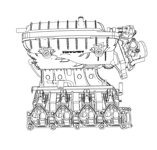
The characteristic torque curve of a normally aspirated engine depends mainly on how the engine's average pressure changes over the engine speed range. The average pressure is proportional to the volume of the air mass present in the cylinder when the intake valve is closed. The design of the intake system determines how large an air mass can be drawn into a cylinder at a given engine speed. Unlike the resonance intake manifold tuning that varies the intake runner length, the port deactivation intake manifold runner control uses the port deactivation valves in order to achieve maximum performance and efficiency over the entire operating range of the engine. These valves are located in the intake manifold, mounted one of each cylinder's intake ports.
The port deactivation valve flap is normally open. When the engine speed and load are below a calibrated threshold, the ECM provides a ground to the port deactivation valve solenoid, energising the port deactivation valve solenoid and allowing a vacuum from the vacuum tank to be applied to the port deactivation valve actuator. Then the actuator closes the port deactivation valve for an increased charge velocity in the intake port and for a swirl in the combustion chamber, which increases thermal efficiency. During higher engine speeds and loads, the port deactivation valve returns to the open position.
The port deactivation intake manifold tuning system consists of the following components:
| • | The port deactivation (PDA) valve solenoid |
| • | The port deactivation (PDA) valve actuator |
| • | The port deactivation (PDA) valve |
Ignition voltage is supplied directly to the port deactivation solenoid valve. The engine control module (ECM) controls the port deactivation solenoid valve by grounding the control circuit via an internal driver switch. The primary function of the driver is to supply ground for the port deactivation solenoid valve. The ECM can determine if the control circuit is open, shorted to ground, or shorted to a voltage by monitoring the voltage on the control circuit.
| © Copyright Chevrolet. All rights reserved |


