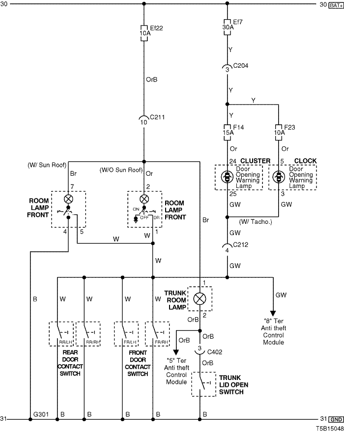
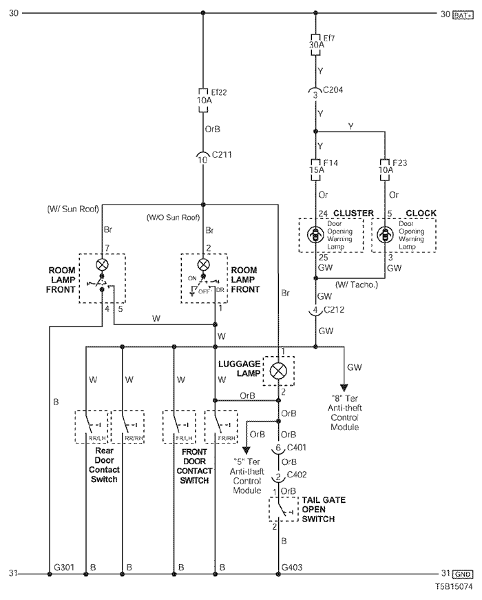
14. LAMPS (ROOM, TRUNK ROOM & DOOR OPENING WARNING) CIRCUIT
1) NOTCH BACK
a. CONNECTOR INFORMATION
CONNECTOR NO
(PIN NO, COLOR) | CONNECTING WIRING HARNESS | CONNECTOR POSITION |
| C204 (4 Pin, White) | Front – IP | Under I/P Fuse Block |
| C211 (22 Pin, Yellow) | Front – Body | Under Left A Pillar |
| C212 (10 Pin, Black) | IP – Body | Under Left A Pillar |
| C402 (4 Pin, White) | Trunk – Body (N/B) | Behind Left Trunk Room Panel |
| G301 | Body | Behind Co-Driver Left Kick Panel |
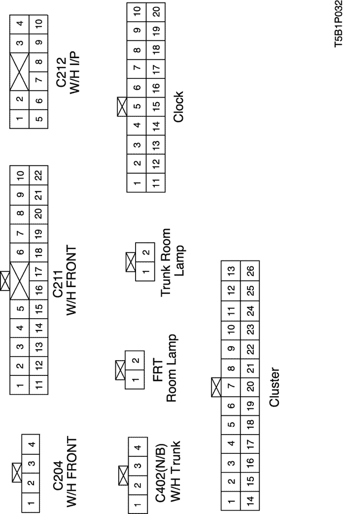
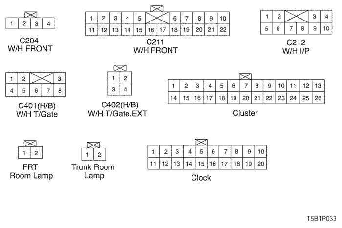
b. CONNECTOR IDENTIFICATION SYMBOL & PIN NUMBER POSITION
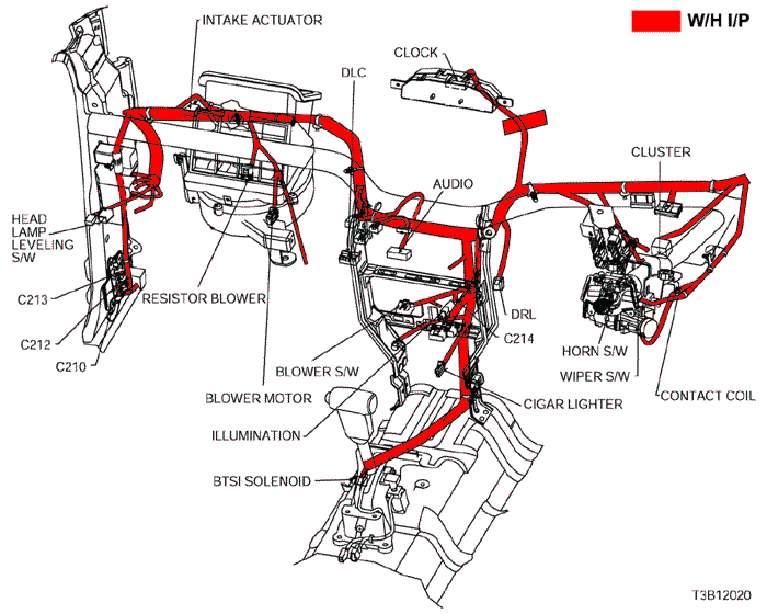
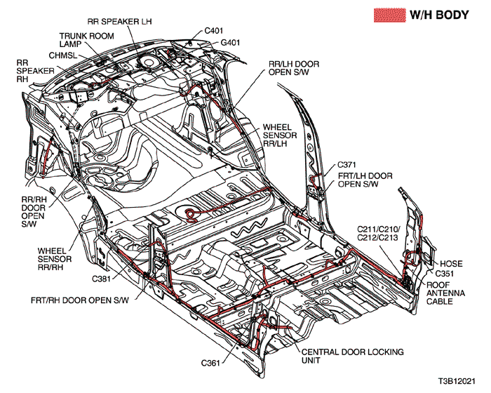
c. POSITION OF CONNECTORS AND GROUNDS
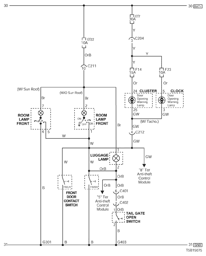
2) HATCH BACK (5HB)
a. CONNECTOR INFORMATION
CONNECTOR NO
(PIN NO, COLOR) | CONNECTING WIRING HARNESS | CONNECTOR POSITION |
| C204 (4 Pin, White) | Front – IP | Under I/P Fuse Block |
| C211 (22 Pin, Yellow) | Front – Body | Under Left A Pillar |
| C212 (10 Pin, Black) | IP – Body | Under Left A Pillar |
| C401 (8 Pin, White) | Tail Gate – Body(H/B) | Under Left C Pillar |
| C402 (4 Pin, White) | Tail Gate.EXT – Tail Gate (H/B) | Under Left Tail Gate |
| G301 | Body | Behind Co-Driver Left Kick Panel |
| G401 | Body (H/B) | Left Tail Gate Panel |
b. CONNECTOR IDENTIFICATION SYMBOL & PIN NUMBER POSITION
c. POSITION OF CONNECTORS AND GROUNDS
3) HATCH BACK (3HB)
a. CONNECTOR INFORMATION
CONNECTOR NO
(PIN NO, COLOR) | CONNECTING WIRING HARNESS | CONNECTOR POSITION |
| C204 (4 Pin, White) | Front – IP | Under I/P Fuse Block |
| C211 (22 Pin, Yellow) | Front – Body | Under Left A Pillar |
| C212 (10 Pin, Black) | IP – Body | Under Left A Pillar |
| C401 (8 Pin, White) | Tail Gate – Body(H/B) | Under Left C Pillar |
| C402 (4 Pin, White) | Tail Gate.EXT – Tail Gate (H/B) | Under Left Tail Gate |
| G301 | Body | Behind Co-Driver Left Kick Panel |
| G401 | Body (H/B) | Left Tail Gate Panel |
b. CONNECTOR IDENTIFICATION SYMBOL & PIN NUMBER POSITION
c. POSITION OF CONNECTORS AND GROUNDS
sm
| © Copyright Chevrolet Europe. All rights reserved |