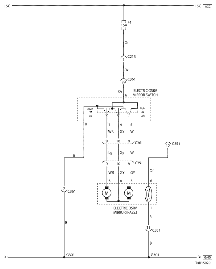
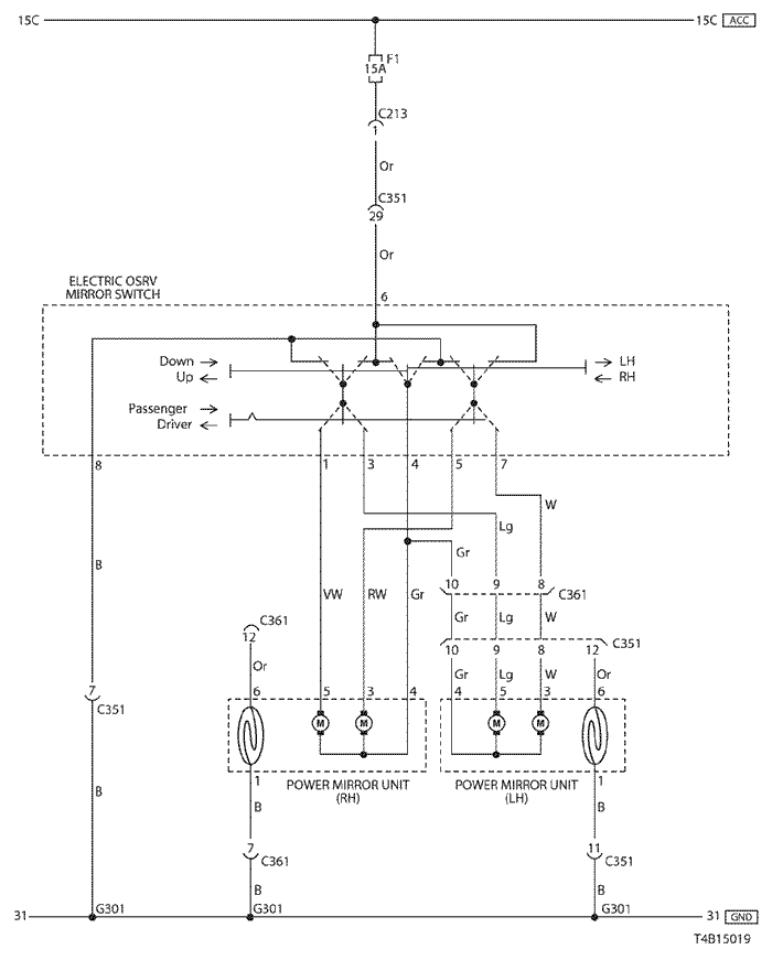
18. ELECTRIC OSRV (OUTSIDE REAR VIEW) MIRROR CIRCUIT
1) PASSENGER ELECTRIC CONTROL
a. CONNECTOR INFORMATION
CONNECTOR NO
(PIN NO, COLOR) | CONNECTING WIRING HARNESS | CONNECTOR POSITION |
| C213 (15 Pin, White) | IP – Body | Under Left A Pillar |
| C351 (29 Pin, White) | Body – Co-Driver Door | Under Left A Pillar |
| C361 (29 Pin, White) | Body - Driver Door | Under Right A Pillar |
| G102 | Front | Behind Left Head Lamp |
| G301 | Body | Behind Co-Driver Left Kick Panel |
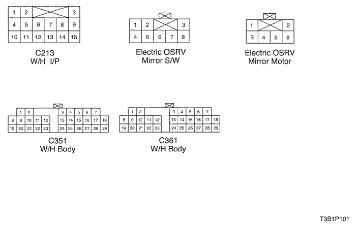
b. CONNECTOR IDENTIFICATION SYMBOL & PIN NUMBER POSITION
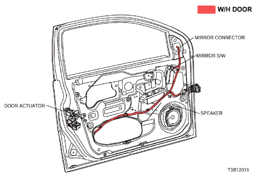
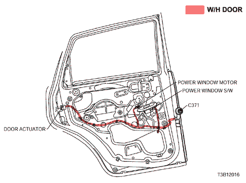
c. POSITION OF CONNECTORS AND GROUNDS
2) DRIVER & PASSENGER ELECTRIC CONTROL
a. CONNECTOR INFORMATION
CONNECTOR NO
(PIN NO, COLOR) | CONNECTING WIRING HARNESS | CONNECTOR POSITION |
| C213 (15 Pin, White) | IP – Body | Under Left A Pillar |
| C351 (29 Pin, White) | Body – Co-Driver Door | Under Left A Pillar |
| C361 (29 Pin, White) | Body - Driver Door | Under Right A Pillar |
| G102 | Front | Behind Left Head Lamp |
| G301 | Body | Behind Co-Driver Left Kick Panel |
b. CONNECTOR IDENTIFICATION SYMBOL & PIN NUMBER POSITION
c. POSITION OF CONNECTORS AND GROUNDS
sm
| © Copyright Chevrolet Europe. All rights reserved |