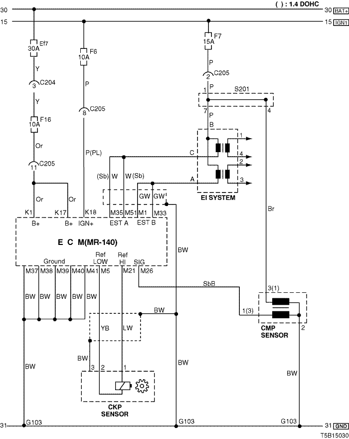
2. ECM (ENGINE CONTROL MODULE) : MR - 140
1) BATTERY POWER SUPPLY, GROUND, EI SYSTEM, CKP SENSOR & CMP SENSOR CIRCUIT
a. CONNECTOR INFORMATION
CONNECTOR NO
(PIN NO, COLOR) | CONNECTING WIRING HARNESS | CONNECTOR POSITION |
| C204 (4 Pin, White) | Front – IP | Under I/P Fuse Block |
| C205 (18 Pin, Gray) | IP – Engine | Behind I/P Fuse Block |
| G103 | Engine | Next to #4 Injector |
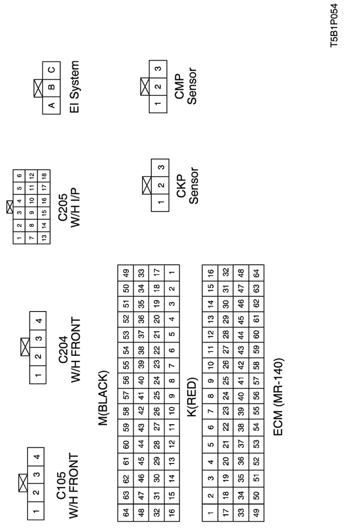
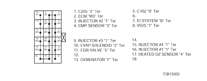
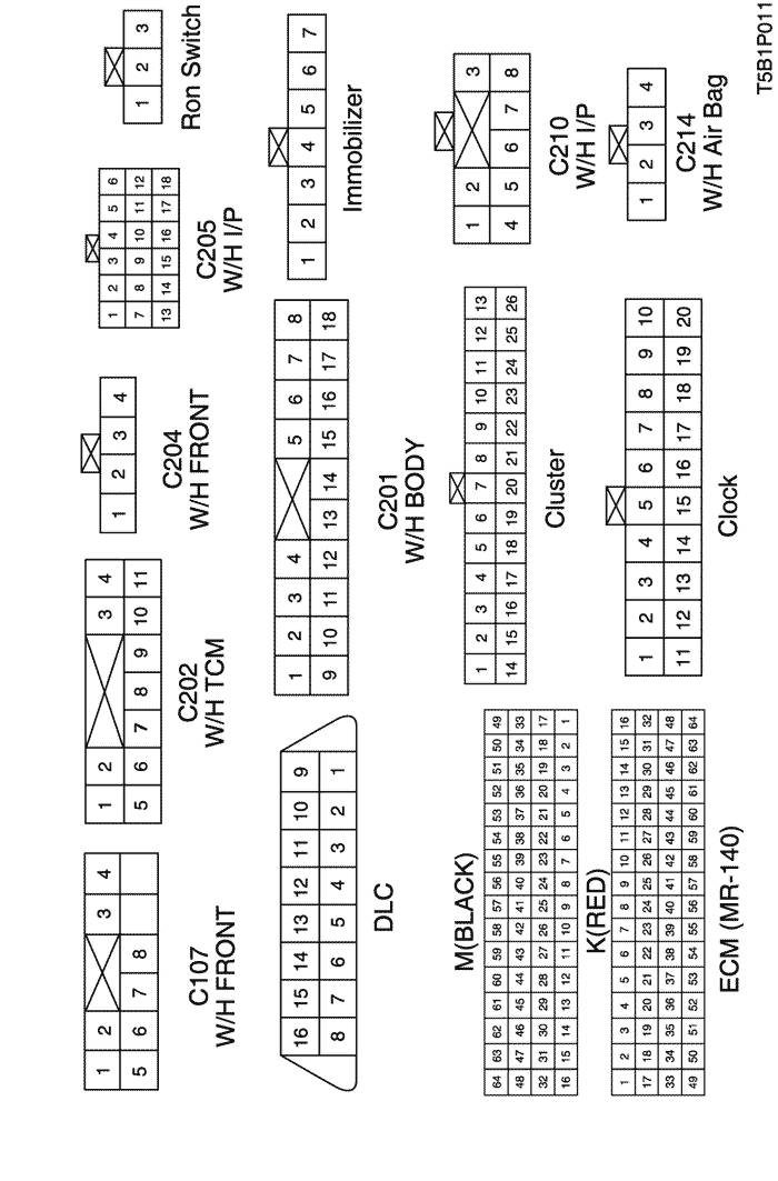
b. CONNECTOR IDENTIFICATION SYMBOL & PIN NUMBER POSITION
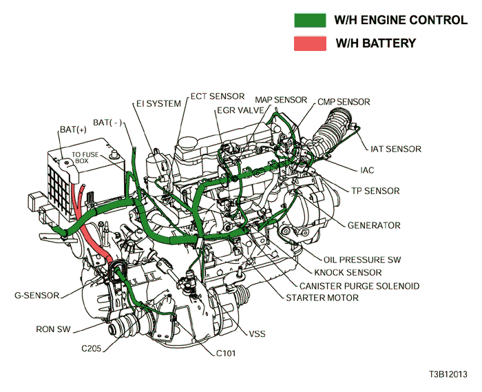
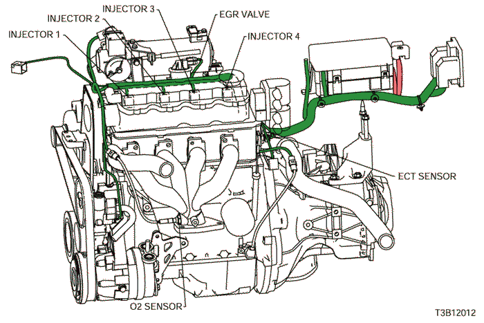
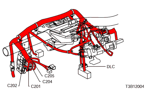
c. POSITION OF CONNECTORS AND GROUNDS
d. SPLICE PACK
S201
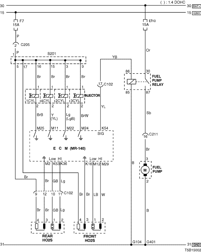
2) FUEL PUMP, INJECTOR & O2 SENSOR CIRCUIT
a. CONNECTOR INFORMATION
CONNECTOR NO
(PIN NO, COLOR) | CONNECTING WIRING HARNESS | CONNECTOR POSITION |
| C102 (20 Pin, White) | Engine – Front | Engine Room Fuse Block |
| C205 (18 Pin, Gray) | IP – Engine | Behind I/P Fuse Block |
| C211 (22 Pin, Yellow) | Front – Body | Under Left A Pillar |
| G104 | Front | Behind Right Head Lamp |
| G401 | Body (N/B) | Upper Left Trunk Room Panel |
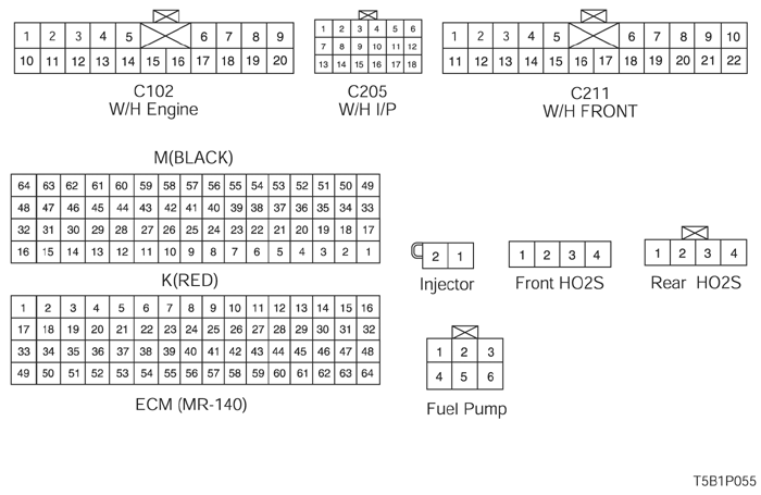
b. CONNECTOR IDENTIFICATION SYMBOL & PIN NUMBER POSITION
c. POSITION OF CONNECTORS AND GROUNDS
d. SPLICE PACK
S201
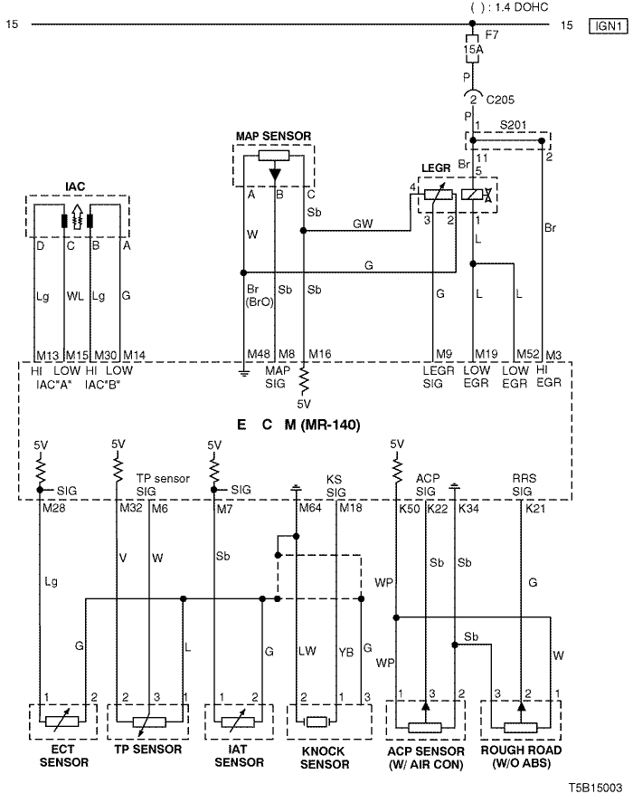
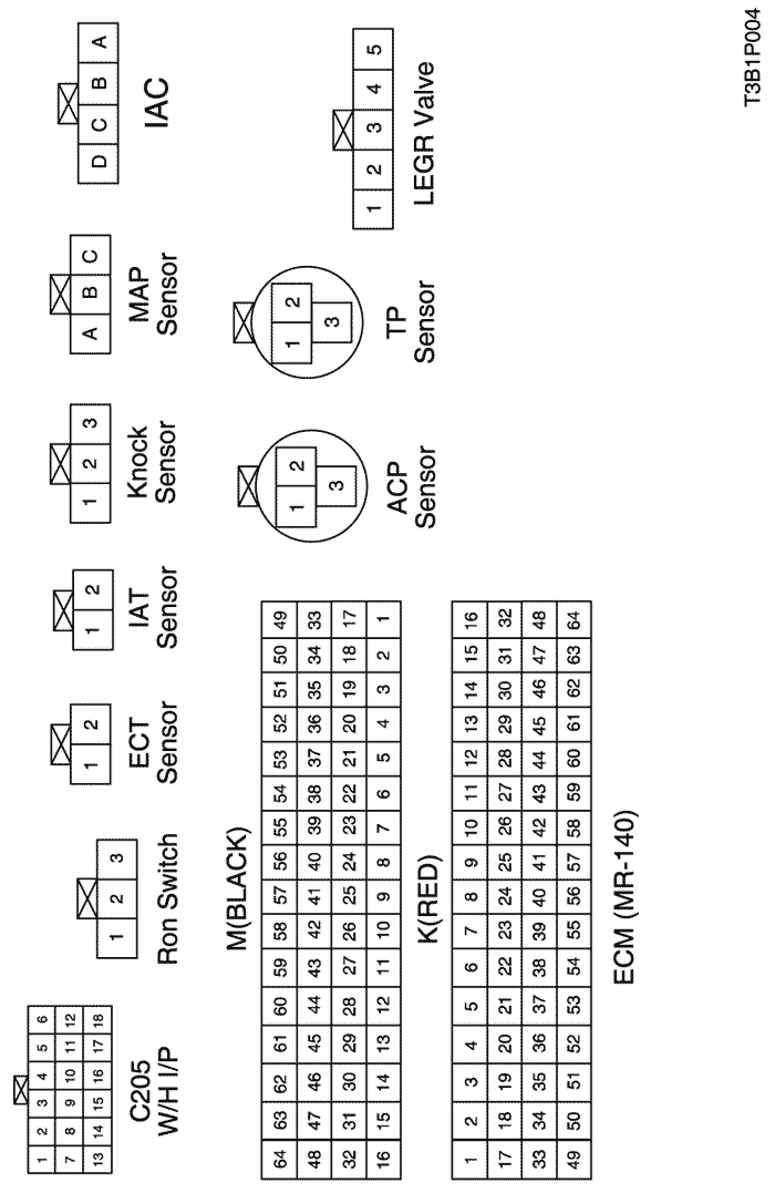
3) IAC, SENSOR (MAP, ECT, TP, KNOCK, ACP), LEGR & ROUGH ROAD SENSOR CIRCUIT
a. CONNECTOR INFORMATION
CONNECTOR NO
(PIN NO, COLOR) | CONNECTING WIRING HARNESS | CONNECTOR POSITION |
| C205(18 Pin, Gray) | IP – Engine | Behind I/P Fuse Block |
b. CONNECTOR IDENTIFICATION SYMBOL & PIN NUMBER POSITION
c. POSITION OF CONNECTORS AND GROUNDS
d. SPLICE PACK
S201
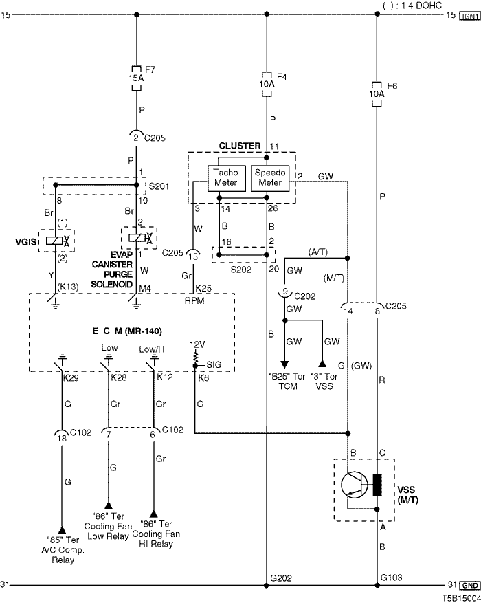
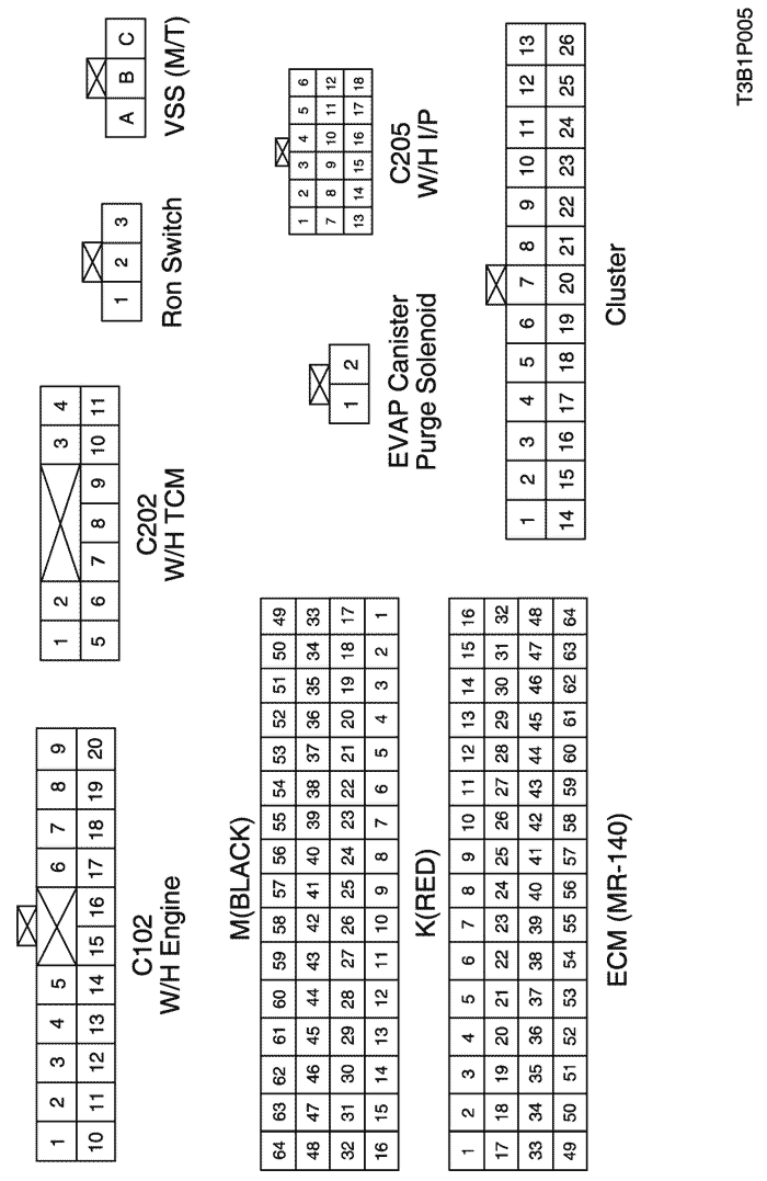
4) EVAP CANISTER PURGE SOLENOID, CLUSTER & VSS CIRCUIT
a. CONNECTOR INFORMATION
CONNECTOR NO
(PIN NO, COLOR) | CONNECTING WIRING HARNESS | CONNECTOR POSITION |
| C102 (20 Pin, White) | Engine – Front | Engine Room Fuse Block |
| C202 (11 Pin, White) | TCM – IP | Behind I/P Fuse Block |
| C205 (18 Pin, Gray) | IP – Engine | Behind I/P Fuse Block |
| G103 | Engine | Next to #4 Injector |
| G202 | IP | Behind Right Ashtray |
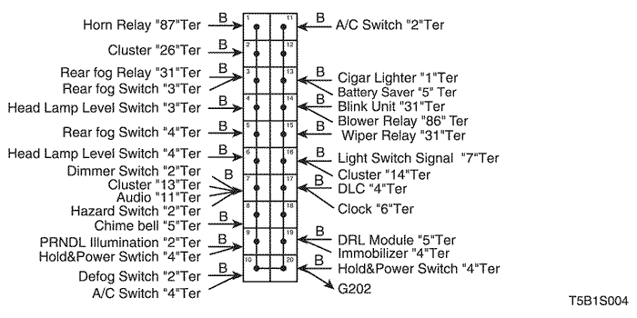
b. CONNECTOR IDENTIFICATION SYMBOL & PIN NUMBER POSITION
c. POSITION OF CONNECTORS AND GROUNDS
d. SPLICE PACK
S201
S202
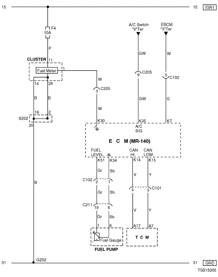
5) CLUSTER, FUEL PUMP & TCM CIRCUIT
a. CONNECTOR INFORMATION
CONNECTOR NO
(PIN NO, COLOR) | CONNECTING WIRING HARNESS | CONNECTOR POSITION |
| C101 (4 Pin, Black) | Engine – TCM | Behind Coolant Reservoir |
| C102 (20 Pin, White) | Engine – Front | Engine Room Fuse Block |
| C205 (18 Pin, Gray) | IP – Engine | Behind I/P Fuse Block |
| C211(22 Pin, Yellow) | IP – Body | Under Left A Pillar |
| G202 | IP | Behind Right Ashtray |
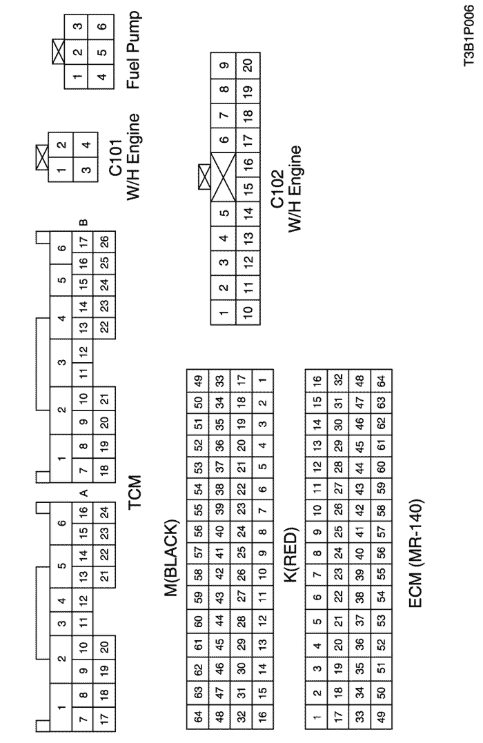
b. CONNECTOR IDENTIFICATION SYMBOL & PIN NUMBER POSITION
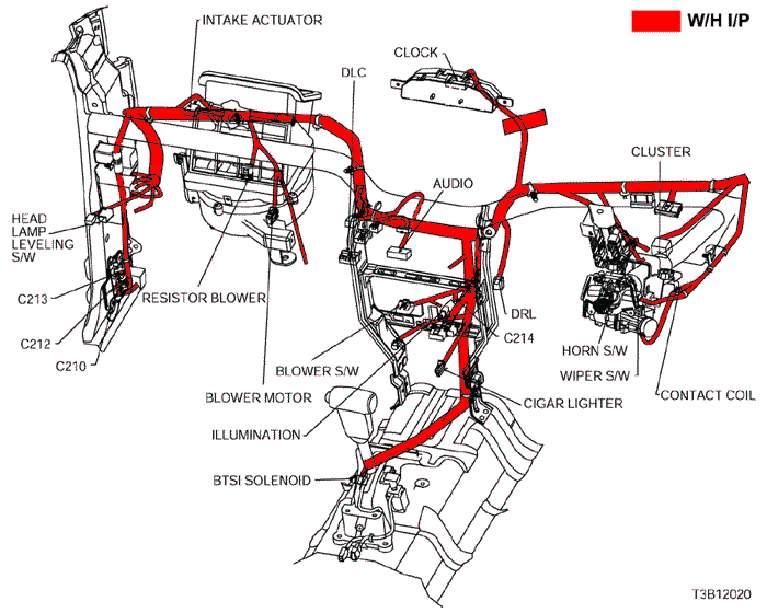
c. POSITION OF CONNECTORS AND GROUNDS
d. SPLICE PACK
S202
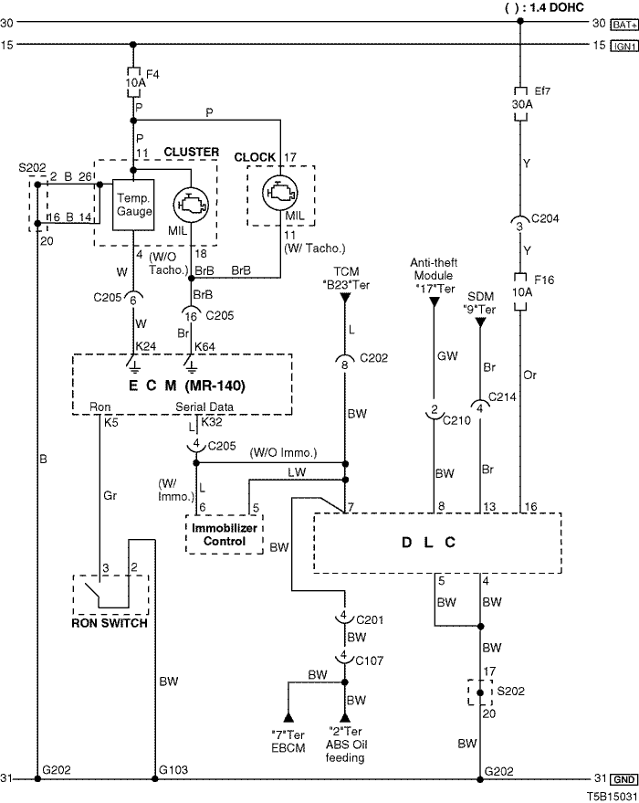
6) DLC, MIL & RON SWITCH CIRCUIT
a. CONNECTOR INFORMATION
CONNECTOR NO
(PIN NO, COLOR) | CONNECTING WIRING HARNESS | CONNECTOR POSITION |
| C107 (4 Pin, Black) | Front – Body | Behind Left A Pillar |
| C201 (18 Pin, Blue) | Body - IP | Under I/P Fuse Black |
| C202 (11 Pin, White) | TCM – IP | Behind I/P Fuse Block |
| C204 (4 Pin, White) | Front – IP | Under I/P Fuse Block |
| C205 (18 Pin, Gray) | IP – Engine | Behind I/P Fuse Block |
| C210 (8 Pin, Green) | IP – Body | Under Left A Pillar |
| C214 (4 Pin, White) | Air Bag - IP | Behind Audio |
| G103 | Engine | Next to #4 Injector |
| G202 | IP | Behind Right Ashtray |
b. CONNECTOR IDENTIFICATION SYMBOL & PIN NUMBER POSITION
c. POSITION OF CONNECTORS AND GROUNDS
d. SPLICE PACK
S202
sm
| © Copyright Chevrolet Europe. All rights reserved |