21. CLUSTER
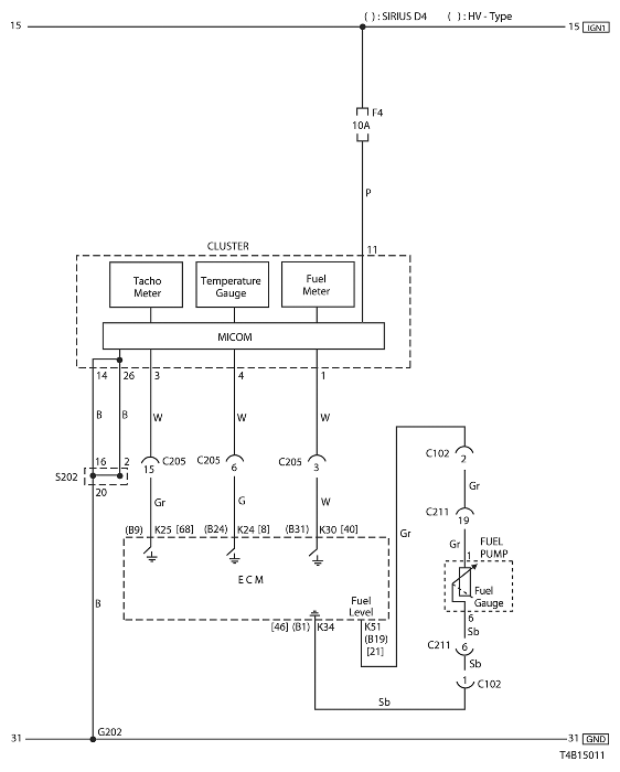
1) TEMPERATURE GAUGE, TACHOMETER & FUEL METER CIRCUIT
a. CONNECTOR INFORMATION
CONNECTOR NO
(PIN NO, COLOR) | CONNECTING WIRING HARNESS | CONNECTOR POSITION |
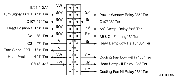
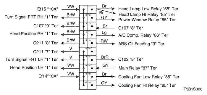
| C102 (20 Pin, White) | Engine – Front | Engine Room Fuse Block |
| C205 (18 Pin, Gray) | IP – Engine | Behind I/P Fuse Block |
| C211 (22 Pin, Yellow) | Front – Body | Under Left A Pillar |
| G202 | IP | Behind Right Ashtray |
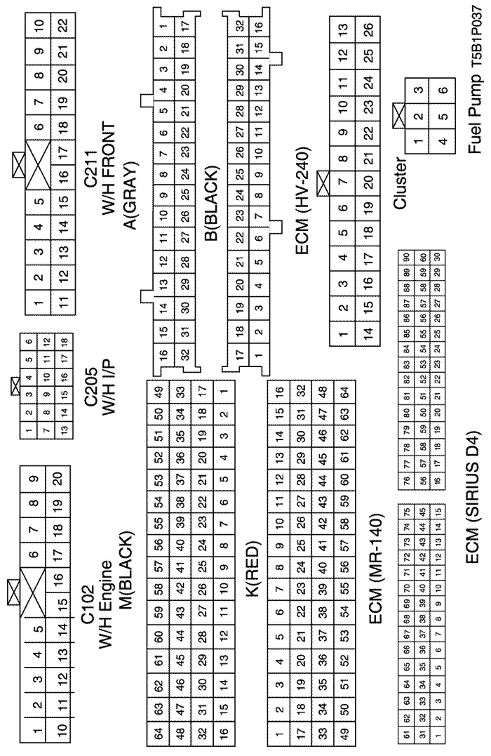
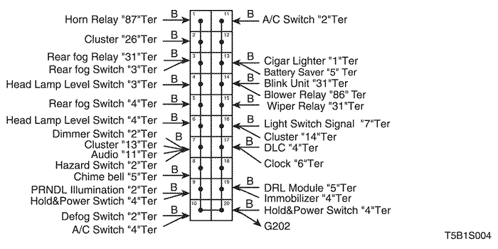
b. CONNECTOR IDENTIFICATION SYMBOL & PIN NUMBER POSITION
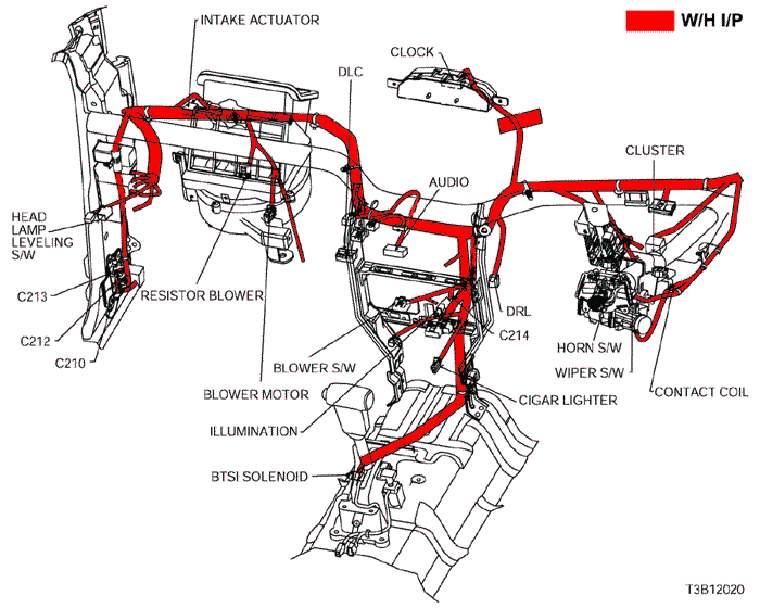
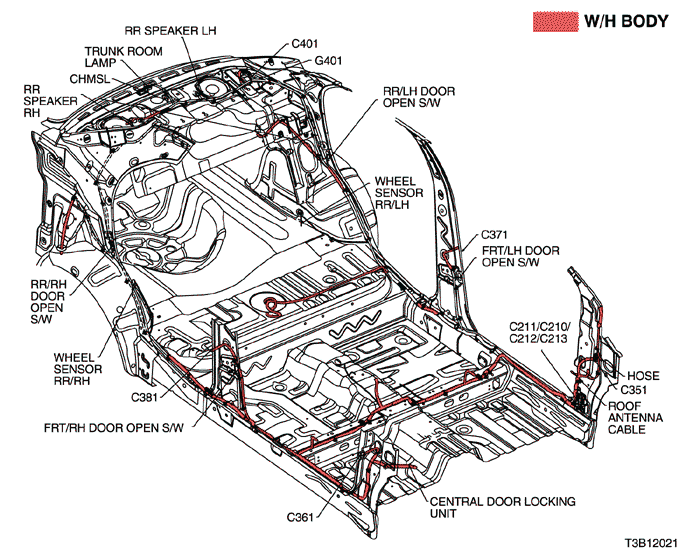
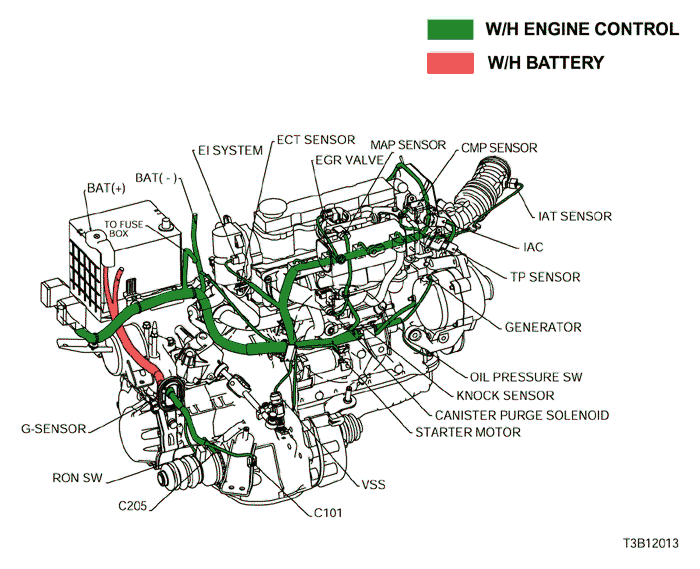
c. POSITION OF CONNECTORS AND GROUNDS
d. SPLICE PACK
S202
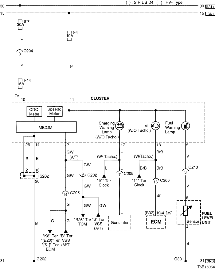
2) ODOMETER, SPEEDOMETER & WARNING(CHARGING, MIL, FUEL) LAMP CIRCUIT
a. CONNECTOR INFORMATION
CONNECTOR NO
(PIN NO, COLOR) | CONNECTING WIRING HARNESS | CONNECTOR POSITION |
| C202 (11 Pin, White) | TCM – IP | Behind I/P Fuse Block |
| C204 (4 Pin, White) | Front – IP | Under I/P Fuse Block |
| C205 (18 Pin, Gray) | IP – Engine | Behind I/P Fuse Block |
| G202 | IP | Behind Right Ashtray |
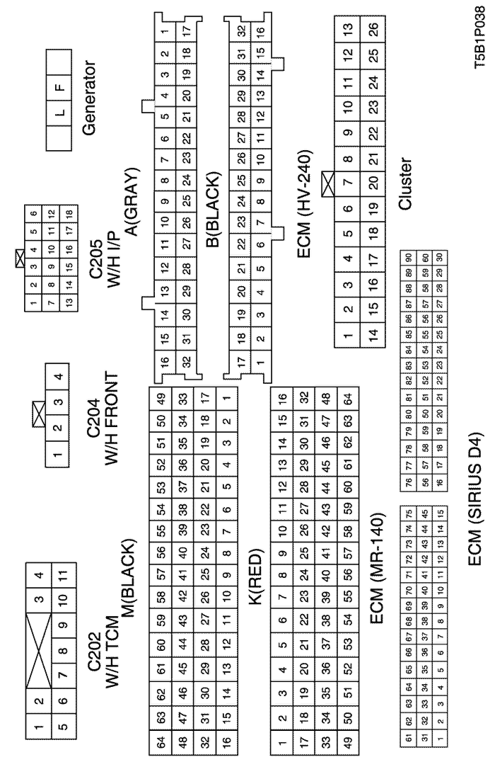
b. CONNECTOR IDENTIFICATION SYMBOL & PIN NUMBER POSITION
c. POSITION OF CONNECTORS AND GROUNDS
d. SPLICE PACK
S202
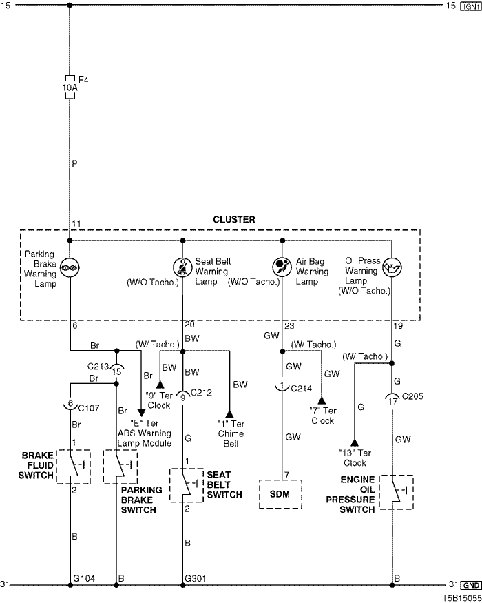
3) WARNING (PARKING BRAKE, SEAT BELT, AIR BAG, OIL PRESSURE) LAMP CIRCUIT
a. CONNECTOR INFORMATION
CONNECTOR NO
(PIN NO, COLOR) | CONNECTING WIRING HARNESS | CONNECTOR POSITION |
| C107 (10 Pin, Black) | Front – Body | Behind Left A Pillar |
| C205 (18 Pin, Gray) | IP – Engine | Behind I/P Fuse Block |
| C212 (10 Pin, Black) | IP – Body | Under Left A Pillar |
| C213 (15 Pin, White) | IP – Body | Under Left A Pillar |
| C214 (4 Pin, White) | Air Bag - IP | Behind Audio |
| G104 | Front | Behind Right Head Lamp |
| G301 | Body | Behind Co-Driver Left Kick Panel |
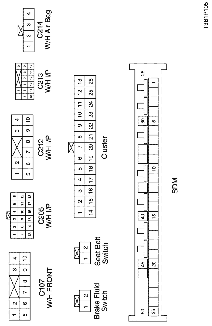
b. CONNECTOR IDENTIFICATION SYMBOL & PIN NUMBER POSITION
c. POSITION OF CONNECTORS AND GROUNDS
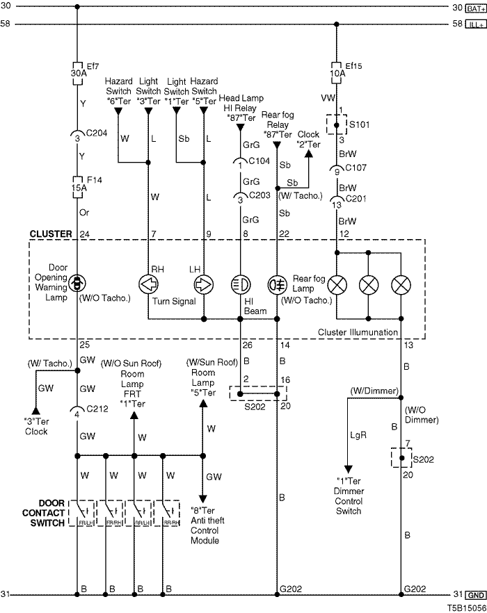
4) INDICATOR LAMP (TURN SIGNAL, HIGH BEAM, REAR FOG), ILLUMINATION LAMP & DOOR OPENING WARNING LAMP CIRCUIT
a. CONNECTOR INFORMATION
CONNECTOR NO
(PIN NO, COLOR) | CONNECTING WIRING HARNESS | CONNECTOR POSITION |
| C104 (15 Pin, White) | Front – Body | Behind Left A Pillar |
| C107 (10 Pin, Black) | Front – Body | Behind Left A Pillar |
| C201 (18 Pin, Blue) | Body – IP | Under I/P Fuse Block |
| C203 (14 Pin, Black) | Body – IP | Under I/P Fuse Block |
| C204 (4 Pin, White) | Front – IP | Under I/P Fuse Block |
| C212 (10 Pin, Black) | IP – Body | Under Left A Pillar |
| G202 | IP | Behind Right Ashtray |
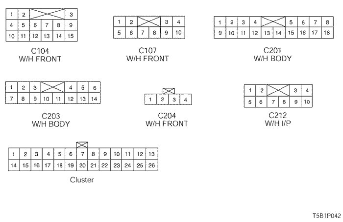
b. CONNECTOR IDENTIFICATION SYMBOL & PIN NUMBER POSITION
c. POSITION OF CONNECTORS AND GROUNDS
d. SPLICE PACK
S101 (MR-140/HV-240)
S101 (SIRIUS D4)
S202
sm
| © Copyright Chevrolet Europe. All rights reserved |