DW100-030 Engine Overhaul Stand
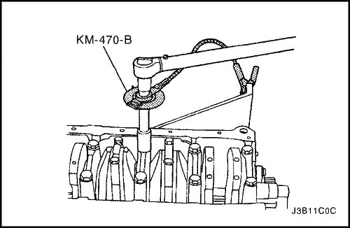
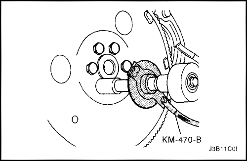
KM-470-B Angular Torque Gauge
J-36972 or KM-635 Crankshaft Rear Oil Seal
- Coat the crankshaft bearings with engine oil.
- If replacing the crankshaft, transfer the reluctor wheel to the new crankshaft.


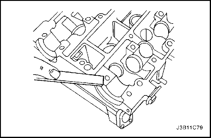
- Install the crankshaft.
- Install the lower crankshaft bearings in the bearing caps.
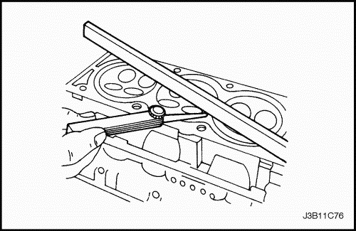
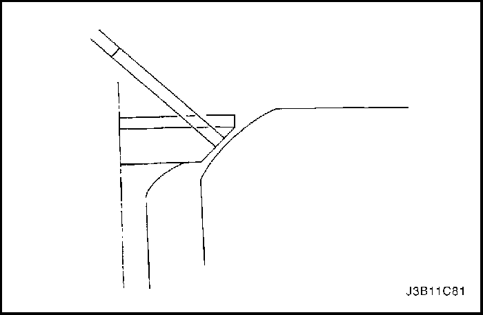
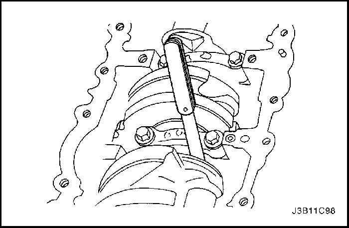
- Inspect the crankshaft end play with the crankshaft bearings installed.
- Check for permissible crankshaft end play. Refer to "Engine Specifications" in this section.

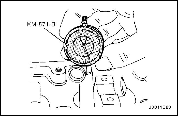
- With the crankshaft mounted on the front and rear crankshaft bearings, check the middle crankshaft journal for permissible out-of-round (runout). Refer to "Engine Specifications"in this section.

Important : Grease the crankshaft journals and lubricate the crankshaft bearings slightly so that the plastic gauging thread does not tear when the crankshaft bearing caps are removed.
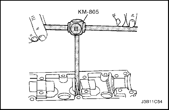
- Inspect all crankshaft bearing clearances using a commercially available plastic gauging (ductile plastic threads).
- Cut the plastic gauging threads to the length of the bearing width. Lay them axially between the crankshaft journals and the crankshaft bearings.
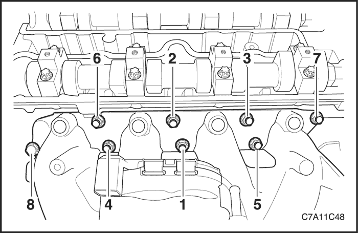
- Install the crankshaft bearing caps and the bolts.
Tighten
Tighten the crankshaft bearing cap bolts to 50 N•m (37 lb-ft) plus 45° and 15°.

- Remove the crankshaft bearing cap bolts and the caps.
- Measure the width of the flattened plastic thread of the plastic gauging using a ruler. (Plastic gauging is available for different tolerance ranges.)
- Inspect the bearing clearance for permissible tolerance ranges. Refer to "Engine Specifications" in this section.
- Apply a bead of adhesive sealing compound to the grooves of the crankshaft bearing caps.
- Install the crankshaft bearing caps to the engine block.
- Tighten the crankshaft bearing caps using new bolts.
Tighten
TightenTighten the crankshaft bearing cap bolts to 50 N•m (37 lb-ft) using a torque wrench. Use the angular torque gauge KM-470-B to tighten the crankshaft bearings another 45° and 15°.
Important : Grease the connecting rod journals and lubricate the connecting rod bearings slightly so that the plastic gauging thread does not tear when the connecting rod bearing caps are removed.
- Inspect all of the connecting rod bearing clearances using a commercially available plastic gauging (ductile plastic threads).
- Cut the plastic gauging threads to the length of the connecting rod bearing width. Lay them axially between the connecting rod journals and the connecting rod bearings.
- Install the connecting rod bearing caps.
Tighten
Tighten the connecting rod bearing cap bolts to 35 N•m (26 lb-ft) using a torque wrench. Use the angular torque gauge KM-470-B to tighten the connecting rod bearing cap bolts another 45° plus 15°.
- Remove the connecting rod bearing caps.
- Measure the width of the flattened plastic thread of the plastic gauging using a ruler. (Plastic gauging is available for different tolerance ranges.)
- Inspect the bearing clearance for permissible tolerance ranges. Refer to "Engine Specifications" in this section.

- Install the connecting rod bearing caps to the connecting rods.
- Tighten the connecting rod bearing caps using new bolts.
Tighten
Tighten the connecting rod bearing cap bolts to 35 N•m (26 lb-ft) using a torque wrench. Use the angular torque gauge KM-470-B to tighten the connecting rod bearing cap bolts another 45° plus 15°.
- Install the oil pump.
- Install the oil pump retaining bolts.
Tighten
Tighten the oil pump retaining bolts to 10 N•m (89 lb-in.).
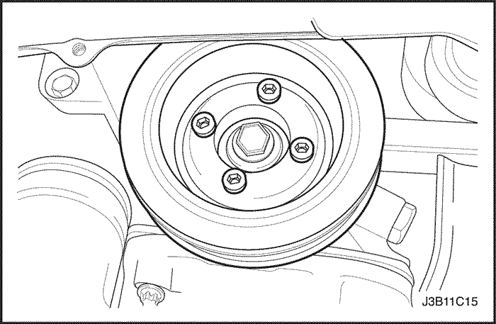
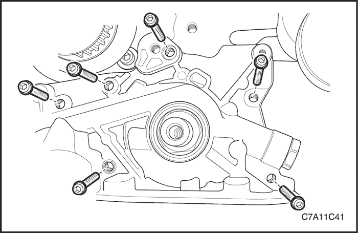
- Install the crankshaft balancer unit assembly.
- Install the crankshaft balancer unit assembly retaining bolts.
Tighten
Tighten the crankshaft balancer unit assembly retaining bolts to 20 N•m (15 lb-ft) and turn the bolts another 45° using the angular torque gauge KM-470-B.
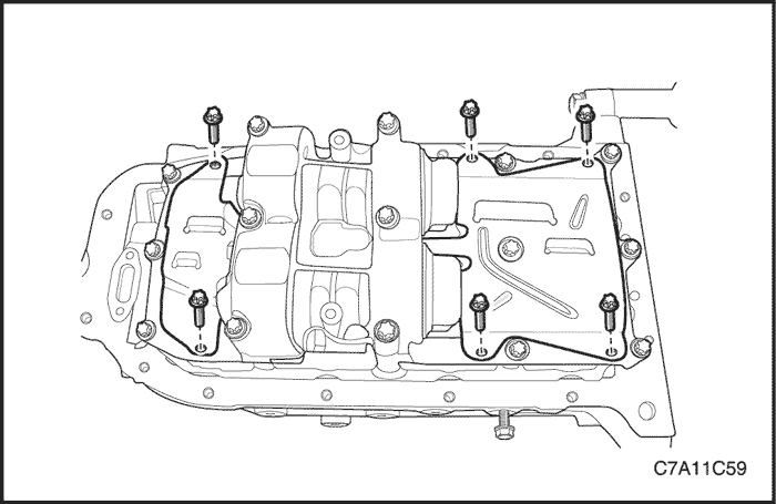
- Install the oil pan scrapers.
- Install the oil pan scraper retaining bolts.
Tighten
Tighten the oil pan scraper retaining bolts to 8 N•m (71 lb-in.).

- Install the oil suction pipe with the new O-ring.
- Install the oil suction pipe retaining bolts.
Tighten
Tighten the oil suction pipe bolts to 8 N•m (71 lb-in.).
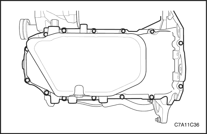
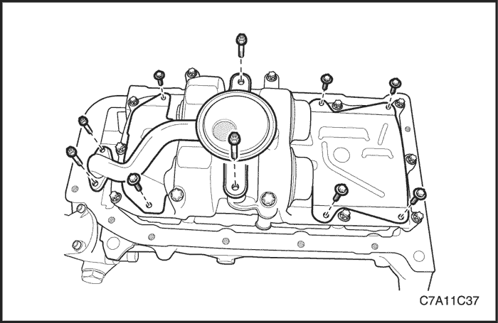
- Coat the sealant on the oil pan mating surface.
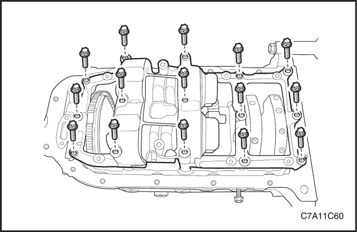
- Install the oil pan.
- Install the oil pan retaining bolts.
Tighten
Tighten the oil pan retaining bolts to 10 N•m (89 lb-in.).

- Rotate the engine on the engine overhaul stand DW100-030.
- Install the rear timing belt cover.
- Install the rear timing belt cover bolts.
Tighten
Tighten the rear timing belt cover bolts to 7 N•m (62 lb-in.).

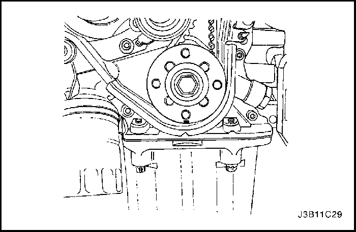
- Install the crankshaft gear and the bolt.
Tighten
Tighten the crankshaft gear bolt to 135 N•m (100 lb-ft) plus 30° plus 10° using the angular torque gauge KM-470-B.
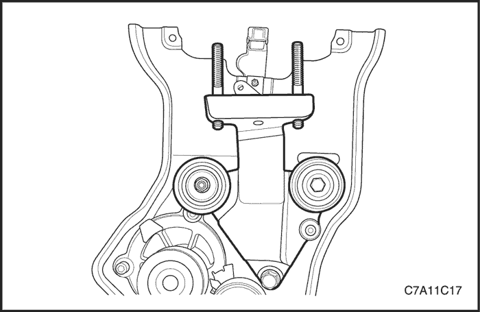
- Install the engine mount adapter support bracket and the bolts.
Tighten
Tighten the engine mount adapter support bracket retaining bolts to 45 N•m (33 lb-ft).
- Install the timing belt idler pulley.
- Install the timing belt idler pulley bolt and nut.
Tighten
Tighten the timing belt idler pulley bolt and nut to 25 N•m (18 lb-ft).
Notice : Take extreme care to prevent any scratches, nicks or damage to the camshafts.
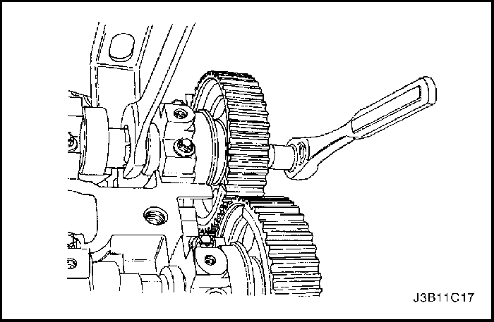
- Install the intake camshaft gear.
- Install the intake camshaft gear bolt while holding the intake camshaft firmly in place.
Tighten
Tighten the intake camshaft gear bolt to 50 N•m (37 lb-ft) plus 60° and 15° using the angular torque gauge KM-470-B.
- Install the exhaust camshaft gear.
- Install the exhaust camshaft gear bolt while holding the exhaust camshaft firmly in place.
Tighten
Tighten the exhaust camshaft gear bolts to 50 N•m (37 lb-ft) plus 60° and 15° using the angular torque gauge KM-470-B.
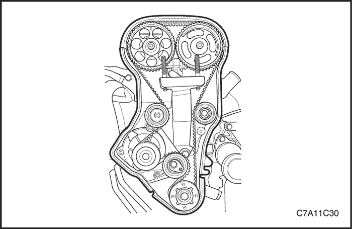
- Install the timing belt automatic tensioner.
Tighten
Tighten the timing belt automatic tensioner bolts to 25 N•m (18 lb-ft).
- Install the timing belt. Refer to "Timing Belt" in this section.
- Adjust the timing belt tension. Refer to "Timing Belt Check and Adjust" in this section.
- Apply a small amount of gasket sealant to the corners of the front camshaft caps and to the top of the rear cylinder head cover to cylinder head seal.
- Install the cylinder head cover and the cylinder head cover gasket. Refer to "Cylinder Head and Gasket"in this section.
Tighten
Tighten the cylinder head cover bolts to 8 N•m (71 lb-in.).
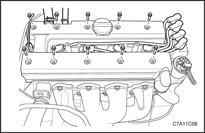
- Connect the ignition wires to the spark plugs.
- Connect the breather hose and PCV hose to the cylinder head cover.

- Install the front timing belt cover.
- Install the front timing belt cover bolts.
Tighten
Tighten the front timing belt cover bolts to 6 N•m (53 lb-in.).
- Install the hoist to the engine support bracket and lift the engine assembly far enough to take the weight off the engine overhaul stand DW100-030.
- Remove the engine from the engine overhaul stand DW100-030.

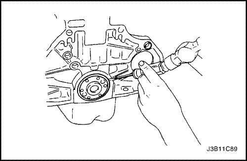
- Install a new crankshaft rear oil seal using the crankshaft rear oil seal installer J-36792.
- Install the flywheel or flexible plate.
- Install the flywheel or flexible plate bolts.
Tighten
Tighten the flywheel bolts to 65 N•m (48 lb-ft).
Use the angular torque gauge KM-470-B to tighten the flywheel bolts another 30° plus 15°.
For the automatic transaxle, tighten the flexible plate bolts to 45 N•m (33 lb-ft).
- Install the engine. Refer to "Engine"in this section.