


Oil Pan
Removal Procedure
- Disconnect the negative battery cable.
- Remove the engine under cover.
- Remove the oil filler cap.
- Remove the oil pan drain plug and drain the oil into a suitable container.
- Remove the exhaust front pipe from the pup converter. Refer to Section 1G2, Engine Exhaust – FAM II 2.4D.
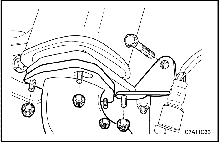
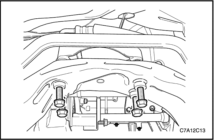
- Remove the oil pan flange-to-transaxle retaining bolts.
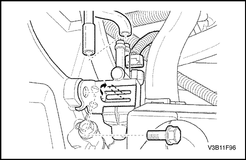
- Remove the transaxle-to-oil pan flange retaining bolt.
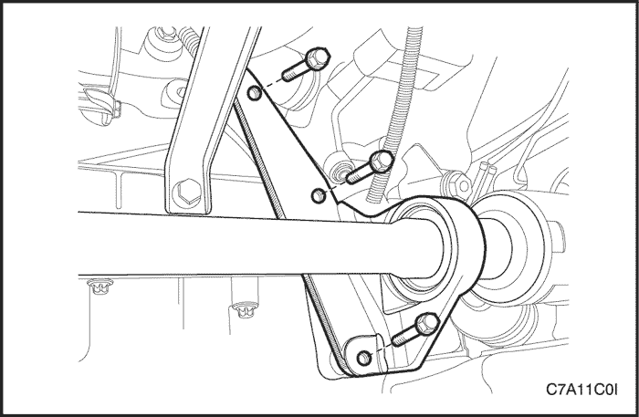
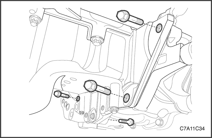
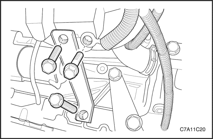
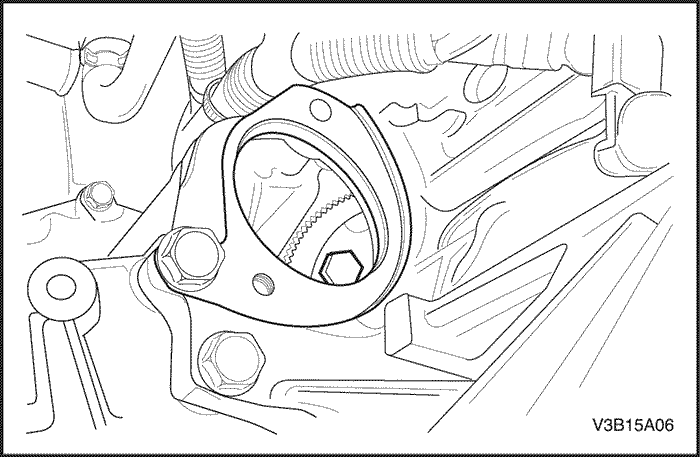
- Remove the interm shaft support bracket bolts from the oil pan and the engine block.
- Remove the interm shaft support bracket.
- For the AWD vehicle, remove the transfer case bracket. Refer to Section 5D, Transfer Case.
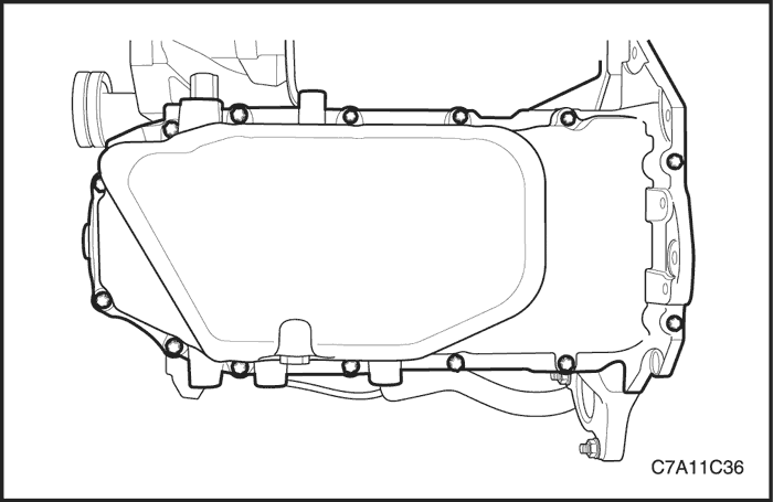
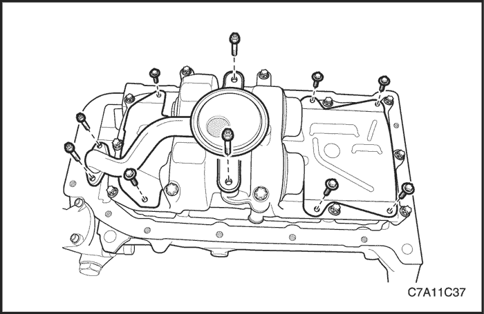
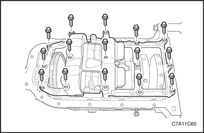
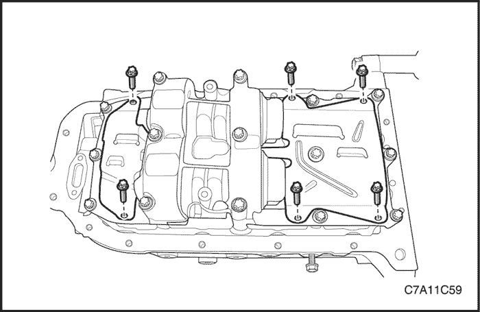
- Remove the oil pan retaining bolts.
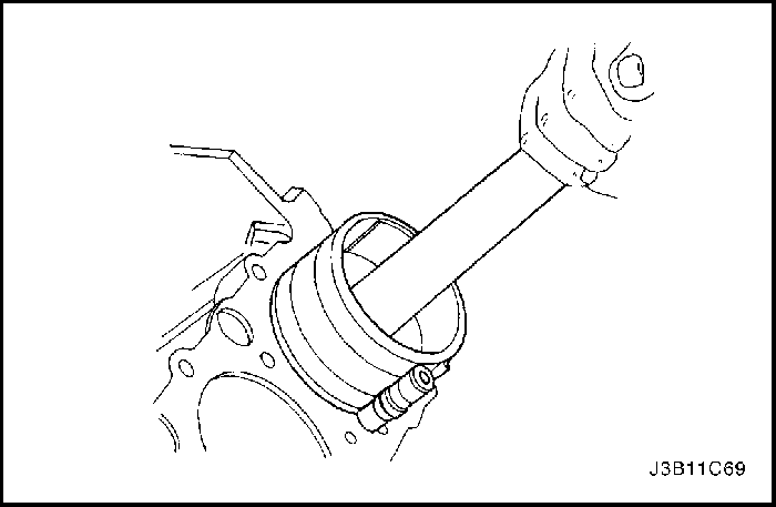
- Remove the oil pan from the engine block with pushing the engine assembly forward.
Cleaning Procedure
- Clean the oil pan sealing surface.
- Clean the engine block sealing surface.
- Clean the oil pan retaining bolts.
- Clean the oil pan attaching bolt holes on the engine block.
- Clean the oil pan scraper.
Installation Procedure
- Coat the oil pan mating surface with sealant.
Important : Install the oil pan within 5 minutes after applying the liquid gasket to the oil pan.
- Install the oil pan to the engine block.
- Install the oil pan retaining bolts.
Tighten
Tighten the oil pan retaining bolts to 10 N•m (89 lb-in.).
- Install the oil pan flange-to-transaxle retaining bolts.
Tighten
Tighten the oil pan flange-to-transaxle bolts to 50 N•m (37 lb-ft).
- Install the transaxle-to-oil pan flange retaining bolt.
Tighten
Tighten the transaxle-to-oil pan flange bolt to 50 N•m (37 lb-ft).
- Install the interm shaft support bracket.
Tighten
Tighten the interm shaft support bracket bolts to 70 N•m (52 lb-ft).
- For the AWD vehicle, Install the transfer case bracket. Refer to Section 5D, Transfer Case.
- Install the exhaust front pipe to the pup converter. Refer to Section 1G, Engine Exhaust.
Tighten
Tighten the pup converter-to-exhaust front pipe retaining nuts to 40 N•m (30 lb-ft).
Tighten the exhaust front pipe mounting bracket bolt and nut to 40 N•m (30 lb-ft).
- Connect the negative battery cable.
- Install the oil pan drain plug.
Tighten
Tighten the oil pan drain plug to 18 N•m (13 lb-ft).
- Install the engine under cover. Refer to Section 9N, Frame and Underbody.
- Refill the engine crankcase with engine oil.
Oil Pump
Removal Procedure
- Disconnect the negative battery cable.
- Remove the timing belt. Refer to "Timing Belt" in this section.
- Remove the rear timing belt cover. Refer to "Rear Timing Belt Cover" in this section.
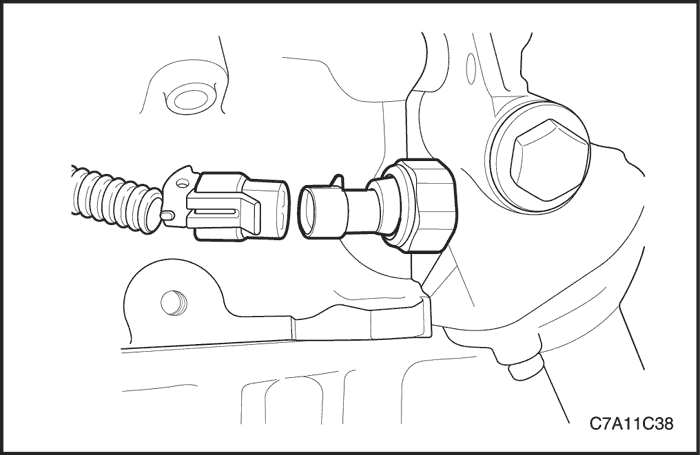
- Disconnect the oil pressure switch connector.
- Remove the oil pan. Refer to "Oil Pan" in this section.
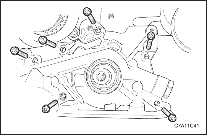
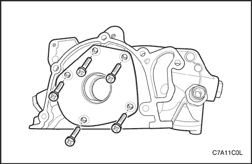
- Remove the oil pump retaining bolts.
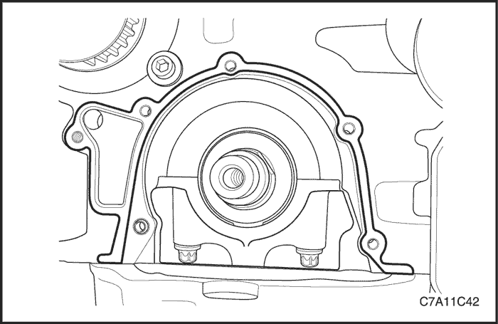
- Carefully separate the oil pump and gasket from the engine block and oil pan.
- Remove the oil pump.
Inspection Procedure
- Clean the oil pump and the engine block gasket mating surface areas.

- Remove the safety relief valve bolt.
- Remove the safety relief valve and the spring.
- Remove the oil pump-to-crankshaft seal.

- Remove the oil pump rear cover.
- Clean the oil pump housing and all the oil pump components.
- Inspect the oil pump components for signs of wear. Replace the worn oil pump parts.
Notice : Pack the oil pump gear cavity with petroleum jelly to ensure an oil pump prime or engine damage could result.
- Coat all the oil pump parts with clean engine oil.
- Apply Loctite 242 to the oil pump rear cover bolts and install the cover and bolts.
Tighten
Tighten the oil pump rear cover bolts to 20 N•m (15 lb-ft).
- Install the safety relief valve, spring, washer and bolt.
Tighten
Tighten the safety relief valve bolt to 30 N•m (22 lb-ft).
Installation Procedure
- Apply Loctite242 to the oil pump bolts and room temperature vulcanizing (RTV) sealant to the new oil pump gasket.
- Install the gasket to the oil pump and install the oil pump to the engine block with bolts.
Tighten
Tighten the oil pump retaining bolts to 10 N•m (89 lb-in.).

- Install a new oil pump-to-crankshaft seal. Coat the lip of the seal with a thin coat of grease.
- Install the oil pan. Refer to "Oil Pan" in this section.
- Connect the oil pressure switch connector.
- Install the rear timing belt cover. Refer to "Rear Timing Belt Cover" in this section.
- Connect the negative battery cable.
Engine Mount Assembly (RH Side)
Tools Required
DW110-060 Engine Assembly Support Fixture
Removal Procedure
Caution : Only lift the engine far enough to take the weight off the engine mount assembly, or damage to the mount and lifting equipment failure may occur.
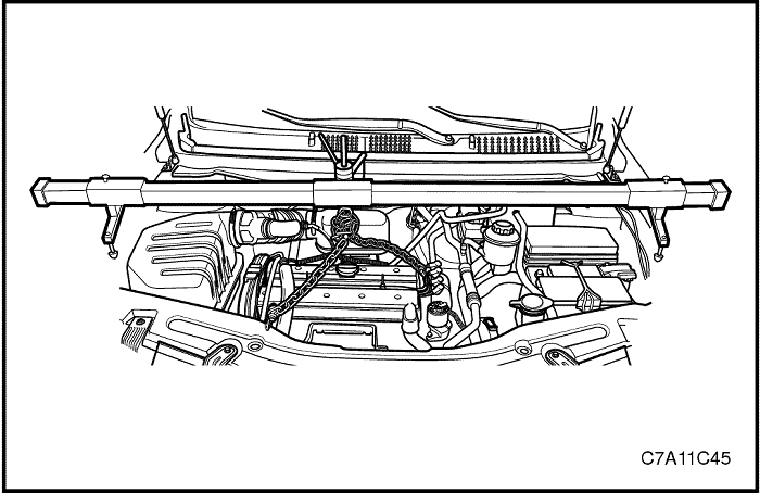
- Support the engine assembly using the engine assembly support fixture DW110-060.

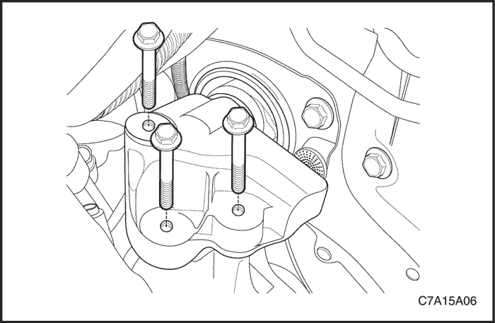
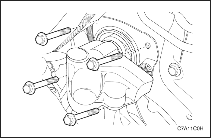
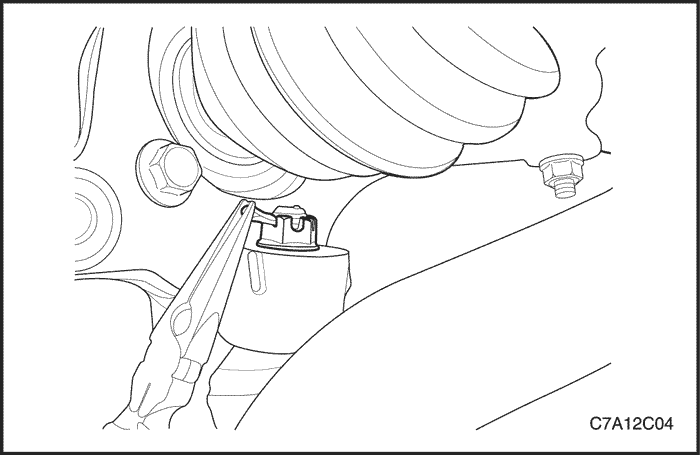
- Remove the engine mount adapter retaining bolts from the engine mount support bracket.
- Remove the engine mount frame side bracket retaining bolt and nuts.
- Remove the engine mount assembly.
Installation Procedure
- Install the engine mount assembly.
Tighten
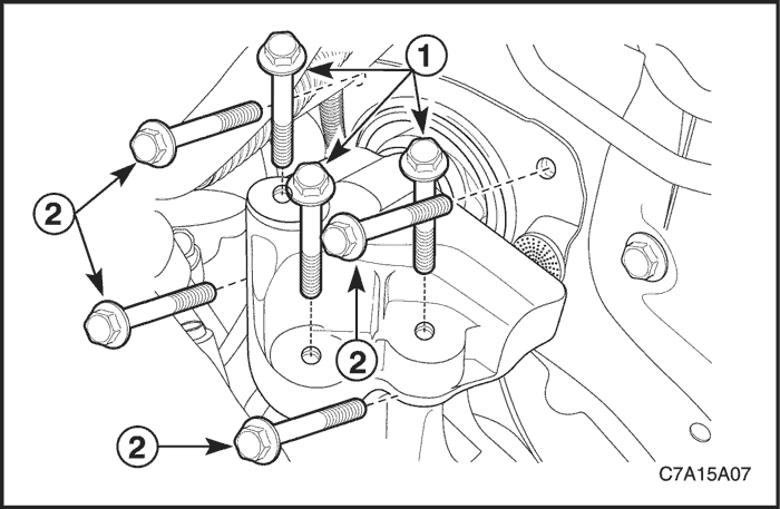
Tighten the engine mount frame side bracket retaining bolt to 100 N•m (74 lb-ft) and nuts to 90 N•m (66 lb-ft).
Tighten the engine mount adapter retaining bolts to 50 N•m (37 lb-ft).
- Remove the engine assembly support fixture DW110-060.
Transaxle Mount Assembly (LH Side)
Tools Required
DW110-060 Engine Assembly Support Fixture
Removal Procedure
- Remove the battery and battery tray. Refer to Section 1E2, Engine Electrical – FAM II 2.4D.
Caution : Only lift the engine far enough to take the weight off the transaxle mount assembly, or damage to the mount and lifting equipment failure may occur.
- Support the engine assembly using the engine assembly support fixture DW110-060.
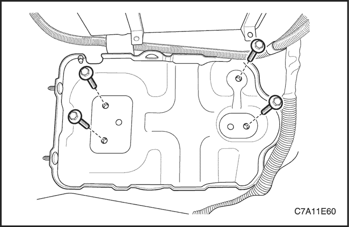
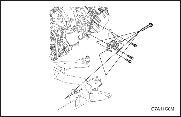
- Remove the transaxle mount bracket retaining bolts from the transaxle.
- Remove the transaxle mount assembly retaining bolts from the left front longitudinal.
- Remove the transaxle mount assembly.
Installation Procedure
- Install the transaxle mount assembly.
Tighten
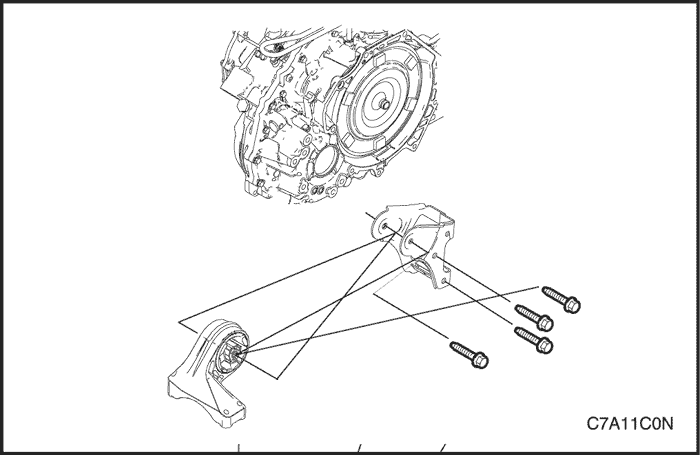
Tighten the transaxle mount assembly retaining bolts (2) to 37 N•m (27 lb-ft).
Tighten the transaxle mount bracket retaining bolts (1) to 50 N•m (37 lb-ft).
- Remove the engine assembly support fixture DW110-060.
- Install the battery and battery tray. Refer to Section 1E2, Engine Electrical – FAM II 2.4D.
Transaxle Front Mount Assembly
Tools Required
DW110-060 Engine Assembly Support Fixture
Removal Procedure
Caution : Only lift the engine far enough to take the weight off the transaxle front mount assembly, or damage to the mount and lifting equipment failure may occur.
- Support the engine assembly using the engine assembly support fixture DW110-060.
- Remove the transaxle front mount-to-cradle through bolt.
- Remove the transaxle front mount retaining bolts from the transaxle.
- Remove the transaxle front mount assembly.
Installation Procedure
- Install the transaxle front mount assembly.
Tighten
Tighten the transaxle front mount retaining bolts to 50 N•m (37 lb-ft).
Caution : Before tightening the transaxle front mount through bolt swing the engine assembly backwards and forwards or from the side to side for the proper alignment.
- Install the transaxle front mount through bolt.
Tighten
Tighten the transaxle front mount-to-cradle through bolt to 90 N•m (66 lb-ft).
Transaxle Rear Mount Assembly
Tools Required
DW110-060 Engine Assembly Support Fixture
Removal Procedure
Caution : Only lift the engine far enough to take the weight off the transaxle rear mount assembly, or damage to the mount and lifting equipment failure may occur.
- Support the engine assembly using the engine assembly support fixture DW110-060.
- Remove the transaxle rear mount-to-bracket through bolt.
- Remove the transaxle rear mount bracket retaining bolts from the transaxle.
- Remove the transaxle rear mount bracket.
- Remove the transaxle rear mount retaining bolts from the cradle.
- Remove the transaxle rear mount.
Installation Procedure
- Install the transaxle rear mount to the cradle.
Tighten
Tighten the transaxle rear mount retaining bolts to 90 N•m (66 lb-ft).
- Install the transaxle rear mount bracket to the transaxle.
Tighten
Tighten the transaxle rear mount bracket retaining bolts to 90 N•m (66 lb-ft).
Caution : Before tightening the transaxle rear mount through bolt, swing the engine assembly backwards and forwards or from the side to side for the proper alignment.
- Install the transaxle rear mount through bolt.
Tighten
Tighten the transaxle rear mount-to-bracket through bolt to 90 N•m (66 lb-ft).
Intake Manifold
Removal Procedure
- Disconnect the negative battery cable.
- Drain the engine coolant. Refer to Section 1D2, Engine Cooling - FAM II 2.4D.
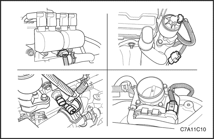
- Disconnect the intake air temperature (IAT) sensor connector.
- Loosen the clamp and disconnect the air cleaner outlet hose from the electronic throttle body with resonator attached.

- Disconnect the electronic throttle control (ETC) sensor connector.
- Disconnect the manifold absolute pressure (MAP) sensor connector.
- Disconnect the coolant hoses form the electronic throttle body.
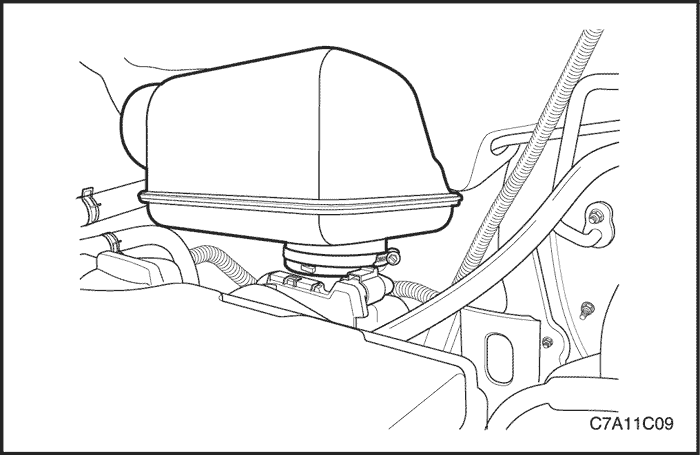
- Disconnect all of the necessary vacuum hoses, including the brake booster vacuum hose at the intake manifold.
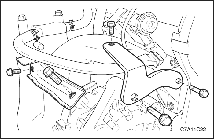
- Remove the generator upper bracket.
- Remove the generator-to-intake manifold strap bracket bolt on the intake manifold and loosen the bolt on the generator.
- Remove the fuel rail assembly. Refer to Section 1F2, Engine Controls - FAM II 2.4D.
- Remove the evaporative (EVAP) emission canister purge solenoid valve. Refer to Section 1F2, Engine Controls - FAM II 2.4D.
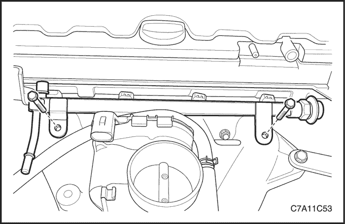
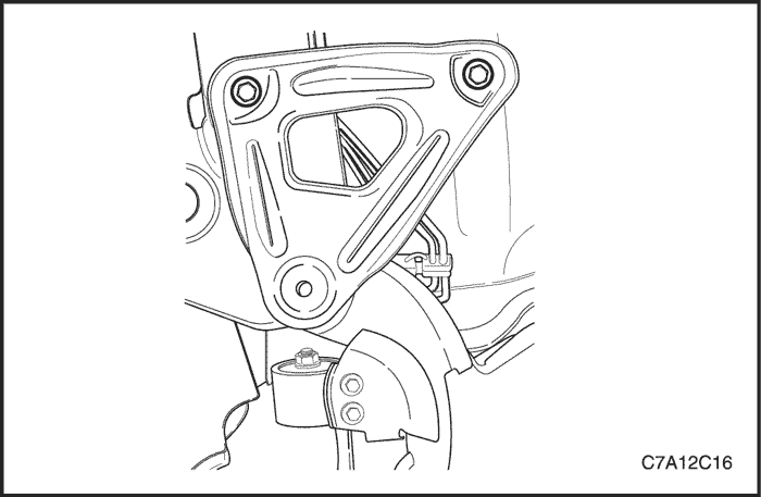
- Remove the intake manifold support bracket bolt at the engine block and the intake manifold.
- Remove the intake manifold support bracket.
- Remove the ground terminal retaining bolt.

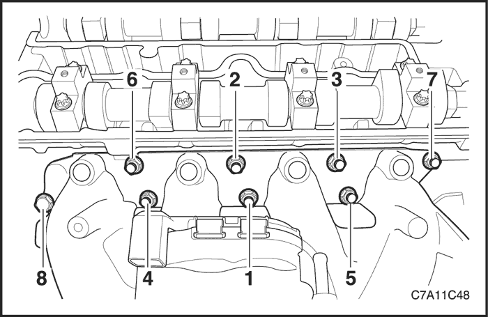
- Remove the intake manifold retaining bolt and nuts in the sequence shown.
- Remove the intake manifold.
- Remove the intake manifold gasket.
- Clean the sealing surfaces of the intake manifold and the cylinder head.
Installation Procedure
- Install a new intake manifold gasket.
- Install the intake manifold.
- Install the intake manifold retaining bolt and nuts in the sequence shown.
Tighten
Tighten the intake manifold retaining bolt and nuts to 22 N•m (16 lb-ft).
- Install the ground wiring terminal retaining bolt to the intake manifold.
- Install the intake manifold support bracket.
Tighten
Tighten the intake manifold support bracket bolts to the intake manifold and cylinder block to 25 N•m (18 lb-ft).
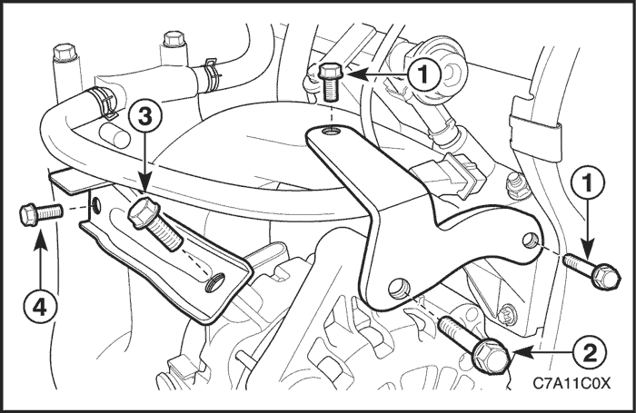
- Install the generator upper bracket.
Tighten
Tighten the generator upper bracket retaining bolts (1) to 25 N•m (18 lb-ft) and the bolt (2) to 35 N•m (26 lb-ft).7.
- Install the generator-to-intake manifold strap bracket.
Tighten
Tighten the generator-to-intake manifold strap bracket retaining bolt (3) to 35 N•m (26 lb-ft) and the bolt (4) to 25 N•m (18 lb-ft).
- Install the fuel rail assembly. Refer to Section 1F2, Engine Controls - FAM II 2.4D.
Tighten
Tighten the fuel rail assembly retaining bolts to 25 N•m (18 lb-ft).
- Install the EVAP emission canister purge solenoid valve.
Tighten
Tighten the evaporative emission canister purge solenoid valve bracket bolt to 5 N•m (44 lb-in.).
- Connect all of the necessary vacuum lines those were previously disconnected.
- Connect the MAP sensor connector.
- Connect the ETC sensor connector.
- Connect the coolant hoses to the electronic throttle body.
- Connect the air cleaner outlet hose to the electronic throttle body with resonator attached.
- Connect the IAT sensor connector.
- Connect the negative battery cable.
- Refill the engine cooling system. Refer to Section 1D2, Engine Cooling - FAM II 2.4D.

Exhaust Manifold
Removal Procedure
- Disconnect the negative battery cable.
- Disconnect the front heated oxygen sensor connector.
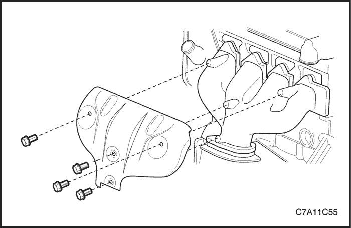
- Remove the exhaust manifold heat shield retaining bolts.
- Remove the exhaust manifold heat shield.
- Remove the pup converter-to-exhaust front pipe retaining nuts.
- Remove the exhaust front pipe mounting bracket bolt and nut.
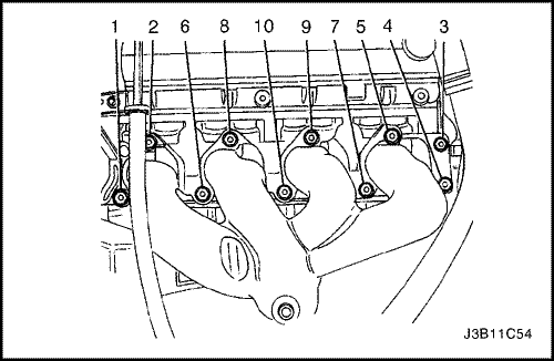
- Remove the exhaust manifold retaining nuts in the sequence shown.
- Remove the exhaust manifold.
- Remove the exhaust manifold gasket.
- Clean the sealing surfaces of the exhaust manifold and the cylinder head.

Installation Procedure
- Install a new exhaust manifold gasket.
- Install the exhaust manifold.
- Install the exhaust manifold retaining nuts and tighten in the sequence shown.
Tighten
Tighten the exhaust manifold retaining nuts to 22 N•m (16 lb-ft).
- Install the exhaust front pipe-to-pup converter. Refer to Section 1G, Engine Exhaust.
Tighten
Tighten the pup converter-to-exhaust front pipe retaining nuts to 40 N•m (30 lb-ft).
Tighten the exhaust front pipe mounting bracket bolt and nut to 40 N•m (30 lb-ft).
- Install the exhaust manifold heat shield.
Tighten
Tighten the exhaust manifold heat shield bolts to 15 N•m (11 lb-ft).
- Connect the front heated oxygen sensor connector.
- Connect the negative battery cable.
Camshaft Gears
Removal Procedure
- Disconnect the negative battery cable.
- Remove the engine beautification cover.
- Disconnect the ignition wires from the spark plugs.
- Disconnect the breather hose and PCV hose from the cylinder head cover.
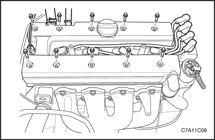
- Remove the cylinder head cover. Refer to "Cylinder Head Cover" in this section.
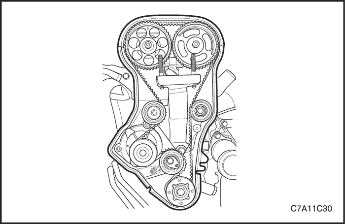
- Remove the timing belt. Refer to "Timing Belt" in this section.
Notice : Take extreme care to prevent any scratches, nicks or damage to the camshafts.
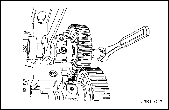
- While holding the intake camshaft firmly in place, remove the intake camshaft gear bolt.
- Remove the intake camshaft gear.
- While holding the exhaust camshaft firmly in place, remove the exhaust camshaft gear bolt.
- Remove the exhaust camshaft gear.
- Remove the camshaft position (CMP) sensor.

Installation Procedure
- Install the camshaft position (CMP) sensor.
Tighten
Tighten the camshaft position sensor bolt to 8 N•m (71 lb-in.).
Notice : Take extreme care to prevent any scratches, nicks or damage to the camshafts.
- Install the intake camshaft gear.
- While holding the intake camshaft firmly in place, install a new intake camshaft gear bolt.
Tighten
Tighten the intake camshaft gear bolt to 50 N•m (37 lb-ft) plus 60° and 15° using the angular torque gauge KM-470-B.
- Install the exhaust camshaft gear.
- While holding the exhaust camshaft firmly in place, install a new exhaust camshaft gear bolt.
Tighten
Tighten the exhaust camshaft gear bolt to 50 N•m (37 lb-ft) plus 60° and 15° using the angular torque gauge KM-470-B.
- Install the timing belt. Refer to "Timing Belt" in this section.
- Apply a small amount of gasket sealant to the corners of the front camshaft caps and to the top of the rear cylinder head cover-to-cylinder head seal.
- Install the cylinder head cover. Refer to "Cylinder Head Cover" in this section.
Tighten
Tighten the cylinder head cover bolts to 8 N•m (71 lb-in.).
- Connect the breather hose and PCV hose to the cylinder head cover.
- Connect the ignition wires to the spark plugs.
- Install the engine beautification cover.
Tighten
Tighten the engine beautification cover bolts and nuts to 8 N•m (71 lb-in.).
- Connect the negative battery cable.
Rear Timing Belt Cover
Tools Required
KM-470-B Angular Torque Gauge
Removal Procedure
- Disconnect the negative battery cable.
- Remove the timing belt. Refer to "Timing Belt" in this section.
- Remove the camshaft gears. Refer to "Camshaft Gears" in this section.
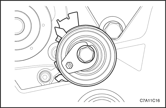
- Remove the timing belt automatic tensioner bolt.
- Remove the timing belt automatic tensioner.
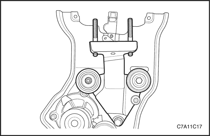
- Remove the timing belt idler pulley retaining bolt and nut.
- Remove the timing belt idler pulleys.
- Remove the engine mount adapter support bracket mounting bolts.
- Remove the engine mount adapter support bracket.
- Remove the camshaft position sensor. Refer to Section 1F2, Engine Controls – FAM II 2.4D.

- Remove the crankshaft gear.
- Remove the rear timing belt cover bolts.
- Remove the rear timing belt cover.
Installation Procedure
- Install the rear timing belt cover.
Tighten
Tighten the rear timing belt cover bolts to 7 N•m (62 lb-in.).
- Install the camshaft position sensor.
Tighten
Tighten the camshaft position sensor bolt to 8 N•m (71 lb-in.).
- Install the engine mount adapter support bracket.
Tighten
Tighten the engine mount adapter support bracket bolts to 45 N•m (33 lb-ft).
- Install the timing belt idler pulleys.
Tighten
Tighten the timing belt idler pulleys bolt and nut to 25 N•m (18 lb-ft).

- Install the crankshaft timing belt drive gear.
Tighten
Tighten the crankshaft gear bolt to 135 N•m (100 lb-ft) plus 30° and plus 10° using the angular torque gauge KM-470-B.
- Install the timing belt automatic tensioner.
Tighten
Tighten the timing belt automatic tensioner to 25 N•m (18 lb-ft).
- Install the camshaft gears. Refer to "Camshaft Gears" in this section.
- Install the timing belt. Refer to "Timing Belt" in this section.
- Connect the negative battery cable.
Engine
Tools Required
EN-48243 Engine Assembly Remove/Install Pallet
EN-48244 Engine Assembly Remove/Install Pallet Supporter
Removal Procedure
- Remove the fuel pump fuse.
- Start the engine. After it stalls, crank the engine for 10 seconds to rid the fuel system of fuel pressure.
- Drain the engine oil.
- Drain the engine coolant. Refer to Section 1D2, Engine Cooling - FAM II 2.4D.
- Drain the power steering oil.
- Drain the transaxle oil. Refer to Section 5A, AISIN 55-51LE Automatic Transaxle or Section 5B, Five-Speed Manual Transaxle (D33).
- Discharge the air conditioning system, if equipped. Refer to Section 7B, Manual Control Heating, Ventilation, and Air Conditioning System.
- Disconnect the intake air temperature (IAT) sensor connector.
- Remove the engine beautification cover.
- Disconnect the breather hose and PCV hose from the cylinder head cover.
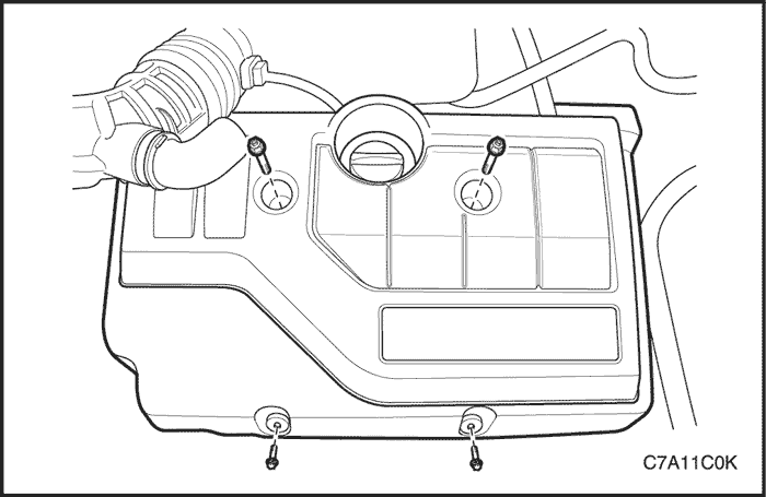
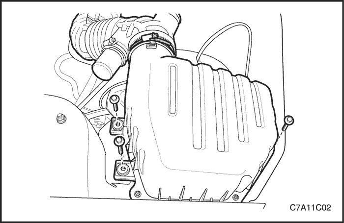
- Remove the air cleaner assembly. Refer to "Air Cleaner Assembly" in this section.
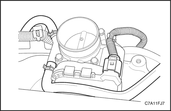
- Remove the resonator from the electronic throttle body.
- Disconnect the upper radiator hose from the thermostat.
- Disconnect the lower radiator hose from the coolant pipe.
- Disconnect the coolant hoses from the electronic throttle body.
- Disconnect the surge tank hose from the cylinder block.
- Disconnect the heater outlet hose from the coolant pipe.
- Disconnect the heater inlet hose from the cylinder head.
- Disconnect the fuel feed line from the fuel rail.
- Disconnect the power steering return hose and the pressure hose from the power steering pump. Refer to Section 6A, Power Steering System.
- Disconnect all of the necessary electrical connectors such as A/C pressure sensor, Exhaust Gas Recirculation valve, Direct Ignition System, Coolant Temperature Sensor, Electronic Throttle Control system, Oxygen sensor, Crankshaft Position sensor, Camshaft Position sensor, Manifold Absolute Pressure sensor, fuel injector, Engine Control Module, knock sensor, alternator and starter terminal etc.
- Remove the ground terminals from the starter, intake manifold and cylinder block.
- Remove all the neccessary parts and disconnect all connectors and cables from the transaxle. Refer to Section 5A, AISIN 55-51LE Automatic Transaxle or Section 5B, Five-Speed Manual Transaxle (D33).
- Disconnect all of the necessary vacuum lines, including the brake booster vacuum hose.
- Remove the A/C compressor. Refer to Section 7B, Manual Control Heating, Ventilation, and Air Conditioning System.
- Remove the engine electrical wires from the engine.
- Remove the pup converter-to-exhaust front pipe retaining nuts.
- Remove the exhaust front pipe mounting bracket bolt and nut.
- Remove the exhaust front pipe from the pup converter. Refer to Section 1G2, Engine Exhaust – FAM II 2.4D.
- For the AWD vehicle, remove the propeller shaft. Refer to Section 3B, Rear Drive Axle.
- Disconnect the stabilizer link. Refer to Section 2D, Rear Suspension.
- Disconnect the tie rod end joint. Refer to Section 2D, Rear Suspension.
- Disconnect the control arm joint. Refer to Section 2D, Rear Suspension.
- Remove the left and right axle shaft. Refer to Section 3A, Automatic Transaxle Drive Axle or Section 3B, Manual Transaxle Drive Axle.
- Remove the power steering gear interm shaft. Refer to Section 6C, Power Steering Gear.
- Remove the cradle support bracket retaining bolts. Refer to Section 2C, Front Suspension.
- Remove the cradle mounting bolts.

Caution : Make sure that all components have to be set on the exact position on the engine assembly remove/install pallet EN-48243 with the pallet supporter EN-48244 as shown.
- 1~4 : Cradle Supporter
- A : Diesel Engine Oil Pan Supporter
- B : FAM II 2.4D Engine Oil Pan Supporter
- C & D : HFV6 3.2L Engine Oil Pan Supporter
- E : Manual Transaxle Supporter
- F : Automatic Transaxle Supporter
- G : Transfer Case Supporter (M/T & A/T)
- H : Transaxle Mount Supporter (M/T & A/T)
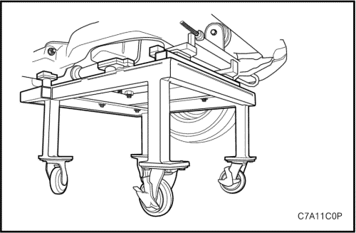
Caution : Only lower the vehicle far enough to take the weight off the engine and transaxle mount, or damage to the mount and pallet/pallet supporter failure may occur.
- Lower the vehicle and position the engine assembly on to the engine assembly remove/install pallet EN-48243 with the pallet supporter EN-48244 to the cradle.
- Remove the engine mount assembly. Refer to "Engine Mount Assembly" in this section.
- Remove the transaxle mount assembly. Refer to "Transaxle Mount Assembly" in this section.
Caution : Make sure that all the cables, connectors and hoses are disconnected from the engine and transaxle assembly.
- Raise the vehicle to remove from the engine and transaxle assembly clear.
- Install the hoist to the engine support bracket and lift the engine assembly far enough to take the weight off the transaxle front and rear mount assembly.
- Remove the transaxle front mount assembly from the cradle. Refer to "Transaxle Front Mount Assembly" in this section.
- Remove the transaxle rear mount assembly from the cradle. Refer to "Transaxle Rear Mount Assembly" in this section.
- Lift the engine assembly and remove the cradle from the engine and transaxle assembly.
- Separate the engine block from the transaxle as follows.
- Remove the torque converter bolts.
- Remove the transaxle to engine block mounting bolts.
- Remove the oil flange to transaxle mounting bolts.
- Remove the starter mounting bolts.
Installation Procedure
- Install the torque converter bolts.
Tighten
Tighten the torque converter bolts to 45 N•m (33 lb-ft).

- Install the transaxle to the engine block.
Tighten
Tighten the transaxle bell housing bolts to 75 N•m (55 lb-ft).
Tighten the oil pan flange-to-transaxle bolts to 50 N•m (37 lb-ft).
- Install the starter mounting bolts.
Tighten
Tighten the starter-to-engine block mounting bolt to 75 N•m (55 lb-ft).
Tighten the transaxle-to-starter mounting bolt to 75 N•m (55 lb-ft).
Caution : Make sure that all components have to be set on the exact position on the engine assembly remove/install pallet EN-48243 with the pallet supporter EN-48244.
- Install the engine and transaxle assembly onto the cradle.
Caution : Before tightening the transaxle front mount through bolt, swing the engine assembly backwards and forwards or from the side to side for the proper alignment.
- Install the transaxle front mount assembly.
Tighten
Tighten the transaxle front mount retaining bolts to 50 N•m (37 lb-ft).
Tighten the transaxle front mount-to-transaxle through bolt to 90 N•m (66 lb-ft).
Caution : Before tightening the transaxle rear mount through bolt, swing the engine assembly backwards and forwards or from the side to side for the proper alignment.
- Install the transaxle rear mount assembly to the cylinder block.
Tighten
Tighten the transaxle rear mount retaining bolts to 90 N•m (66 lb-ft).
Tighten the transaxle rear mount-to-bracket through bolt to 90 N•m (66 lb-ft).
- Lift the vehicle.
- Lower the vehicle and position the engine and transaxle assembly with the cradle attached on to the engine assembly remove/install pallet EN-48243 with the pallet supporter EN-48244 to the vehicle.
- Install the transaxle mount. Refer to "Transaxle Mount Assembly" in this section.
Tighten
Tighten the transaxle mount assembly retaining bolts to 37 N•m (27 lb-ft).
Tighten the transaxle mount bracket retaining bolts to 50 N•m (37 lb-ft).
- Install the engine mount assembly. Refer to "Engine Mount Assembly" in this section.
Tighten
Tighten the engine mount frame side bracket retaining bolt to 100 N•m (74 lb-ft) and nuts to 90 N•m (66 lb-ft).
Tighten the engine mount adapter retaining bolts to 50 N•m (37 lb-ft).
- Remove the engine assembly remove/install pallet EN-48243 with the pallet supporter EN-48244 from the vehicle.
- Install the cradle-to-body mounting bolts. Refer to Section 2C, Front Suspension. Section 2C, Front Suspension.
Tighten
Tighten the cradle mounting bolts to 155 N•m (114 lb-ft).
- Install the cradle support bracket retaining bolts. Refer to Section 2C, Front Suspension. Section 2C, Front Suspension.
Tighten
Tighten the cradle support bracket bolts to 50 N•m (37 lb-ft).
- Install the power steering gear intermediate shaft. Refer to Section 6C, Power Steering Gear.
- Install the left and right axle shaft. Refer to Section 3A, Automatic Transaxle Drive Axle or Section 3B, Manual Transaxle Drive Axle.
- Install the control arm joint. Refer to Section 2D, Rear Suspension.
- Install the tie rod end joint. Refer to Section 2D, Rear Suspension.
- Install the stabilizer link. Refer to Section 2D, Rear Suspension.
- Install the exhaust front pipe-to-pup converter. Refer to Section 1G2, Engine Exhaust – FAM II 2.4D.
Tighten
Tighten the pup converter-to-exhaust front pipe retaining nuts to 40 N•m (30 lb-ft).
Tighten the exhaust front pipe mounting bracket bolt and nut to 40 N•m (30 lb-ft).
- For the AWD vehicle, install the propeller shaft. Refer to Section 3B, Rear Drive Axle.
- Install the engine electrical wires to the engine.
- Connect all of the necessary vacuum lines, including the brake booster vacuum hose.
- Connect the ground terminals.
- Connect all of the necessary electrical connectors.
- Connect the power steering hoses to the power steering pump. Refer to Section 6C, Power Steering Gear.
- Connect the fuel feed line to the fuel rail.
- Connect the heater inlet and outlet hose to the cylinder head.
- Connect all of the necessary cooling hoses to electronic throttle body, thermostat, coolant pipe and cylinder block.
- Install the resonator to the electronic throttle body.
- Install the air cleaner assembly. Refer to "Air Cleaner Assembly" in this section.
- Install the breather hose and PCV hose to the cylinder head cover.
- Connect the intake air temperature (IAT) sensor connector.
- Install the engine beautification cover.
- Install the fuel pump fuse.
- Refill the engine crankcase with engine oil.
- Refill the engine coolant system. Refer to Section 1D2, Engine Cooling - FAM II 2.4D.
- Refill the power steering system and bleed the system. Refer to Section 6A, Power Steering System
- Refill the A/C refrigerant system, if equipped. Refer to Section 7B, Manual Control Heating, Ventilation and Air Conditioning System.
Crankshaft Balancer Unit Assembly
Removal Procedure
- Remove the oil pan. Refer to "Oil Pan" in this section.
- Remove the oil suction pipe with O-ring.
- Remove the oil pan scraper.
- Remove the crankshaft balancer unit assembly retaining bolts.
- Remove the crankshaft balancer unit assembly and the shim.
Adjustment Procedure
- Align the mark on the crankshaft gear with the notch at the bottom of the rear timing belt cover.
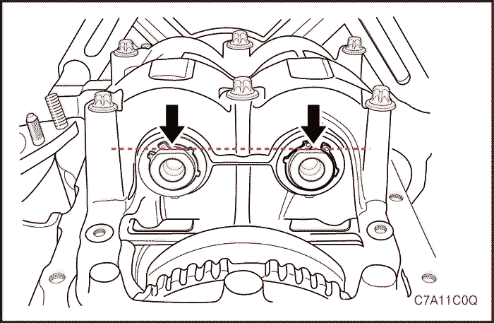
- In this crankshaft position, the flattened side (arrows) of both balancer shafts must face downward (oil pan side) and must be on a horizontal line.
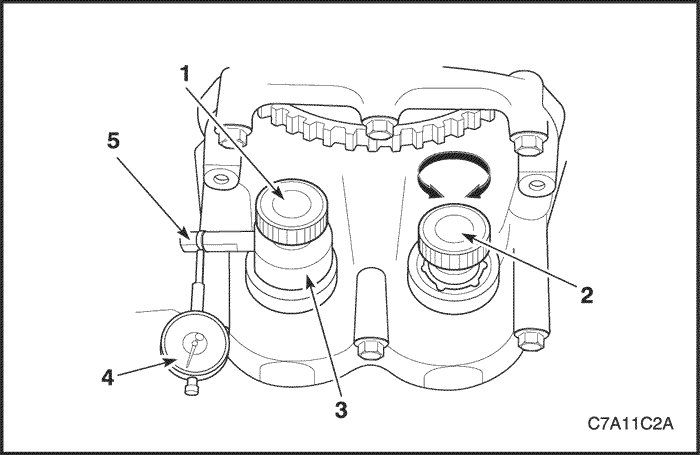
- Screw measuring device KM-949 (3) with long knurled bolt (1) into 1st balancer shaft (intake side) and hand-tighten. The measuring arm (5) must point in “9 o’clock” direction shown in the illustration.
- Install the dial gauge holder with dial gauge (4) on the cylinder block.
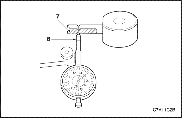
- Place pre-tensioned probe (6) of gauge on measuring arm of measuring device KM-949. The probe must be set precisely between the notch marks, square to the plane surface (7).
- Determine the left and right stops by turning the knurled bolt (2).
- Set the dial of the gauge to zero.
- Use the knurled bolt (2) to move the 2nd balancer shaft (exhaust side) back and forth. Again – simultaneously read off the tooth backlash from the gauge.
- The permissible tooth backlash is : 0.02 mm to 0.06 mm (0.0008 to 0.0024 in.).
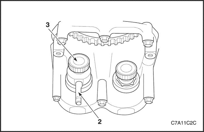
- The tooth backlash must be measured in 4 different positions – turn the crankshaft further at the fastening bolt of the timing belt drive gear by 45° in the engine rotational direction until the measuring arm (2) is at “6 o’clock”.
- Then loosen the knurled bolt (3) fix the measuring arm at “9 o’clock” again and repeat the measurement.
- If the value determined in one of the 4 measurements lies outside the tolerance 0.02 mm to 0.06 mm (0.0008 to 0.0024 in.), the tooth backlash must be adjusted.
- Remove the balancer unit from the cylinder block/crankshaft bearing caps and remove with the balancer piece. The balancer piece has a number (code), for easy assignment. The tooth backlash can be adjusted by using a balancer piece with a different thickness.
Code | Thickness of Balancer piece in mm |
55 | 0.535 – 0.565 |
58 | 0.565 – 0.595 |
61 | 0.595 – 0.625 |
64 | 0.625 – 0.655 |
67 | 0.655 – 0.685 |
70 | 0.685 – 0.715 |
73 | 0.715 – 0.745 |
76 | 0.745 – 0.775 |
79 | 0.775 – 0.805 |
82 | 0.805 – 0.835 |
85 | 0.835 – 0.865 |
Notice : - The next larger of smaller balancer alters the tooth backlash by 0.02 mm (0.0008 in.).
- Example of selection of balancer piece : The installed balancer piece with the code “70” gave a tooth backlash of 0.08 mm (0.0031 in.). If a balancer piece with the code “67” is now installed, the tooth backlash will be approx. 0.06 mm (0.0024 in.).
Caution : Only one balancer piece may be installed.
Installation Procedure
Caution : Before installing the balancer shaft unit assembly, perform the adjustment procedure for the proper operation.
Caution : Take care not to chip or dent teeth when meshing gear sets on assembly.
- Align the mark on the crankshaft gear with the notch at the bottom of the rear timing belt cover.
- Turn the balancer shaft until the flattened side (arrows) of both balancer shafts face downward (oil pan side) and are on a horizontal line.
- Install the selected balancer piece with the balancer shaft unit to the cylinder block.
- Install the crankshaft balancer shaft unit assembly retaining bolts.
Tighten
Tighten the crankshaft balancer shaft unit assembly retaining bolts to 20 N•m (15 lb-ft) and turn the bolts another 45° using the angular torque gauge KM-470-B.
Note : If the balancer shaft unit has to be replaced, use the thickest balancer piece with the code “85” for the initial installation to ensure a tooth backlash in any case.
- Install the oil pan scraper.
Tighten
Tighten the oil pan scraper retaining bolts to 8 N•m (71 lb-in.).
- Install the oil suction pipe with the new O-ring.
Tighten
Tighten the oil suction pipe retaining bolts to 8 N•m (71 lb-in.).
- Install the oil pan. Refer to "Oil Pan" in this section.

Pistons And Connecting Rods
Tools Required
J-8037 Universal Piston Ring Compressor
J-8087 Cylinder Bore Check Gauge
KM-427 Piston Pin Service Set
KM-470-B Angular Torque Gauge
Removal Procedure
- Remove the cylinder head with the intake manifold and exhaust manifold attached. Refer to "Cylinder Head and Gasket" in this section.
- Remove the oil pan. Refer to "Oil Pan" in this section.
- Remove the oil suction pipe and the O-ring.
- Remove the oil pan scraper.
- Remove the crankshaft balancer unit assembly. Refer to "Crankshaft Balancer Unit Assembly" in this section.

- Position the piston to the bottom of the piston stroke.
- Mark the connecting rod cap for position.
- Remove the connecting rod cap bolts.
- Remove the connecting rod cap and the lower connecting rod bearing.
- Remove the upper connecting rod bearing.
Caution : Use care when handling the piston. Worn piston rings are sharp and may cause injury.
- Remove the piston.
- Expand the piston rings by using the universal piston ring compressor J-8037.
- Remove the piston rings.
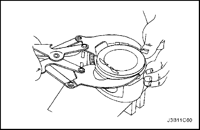
- Remove the piston pin from the piston and connecting rod assembly using the piston pin service set KM-427.
- Separate the piston from the connecting rod.

Inspection Procedure
- Inspect the pistons for the following conditions.
- Eroded areas at the top of the piston
- Worn piston pin bores or worn piston pins
- Scuffed or damaged skirt coating
- Ring grooves for cracks, nicks or burrs that may cause binding, and
- Warped or worn ring lands
- Replace pistons that show any signs of damage or excessive wear.

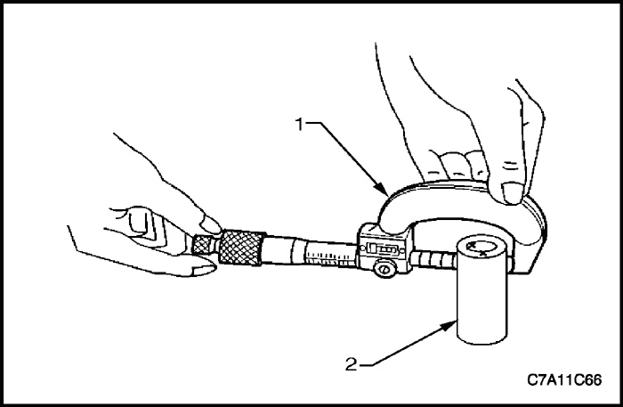
- Measure the piston width using the following procedure.
- Using an outside micrometer, measure the width of the piston at the thrust surfaces of the piston, perpendicular to the piston pin centerline.
- Compare the measurement of the piston to its original cylinder by subtracting the piston width from the cylinder diameter.
- If the clearance obtained through measurement is greater than the provided specifications and the cylinder bores are within specification, replace the piston.
- Measure the piston pin bore to piston pin (2) clearances using the following procedure.
- Piston pin bores and pins must be free of varnish or scuffing.
- Use an outside micrometer (1) to measure the piston pin in the piston contact areas.

- Using an inside micrometer, measure the piston pin bore (1). Compare the result with the piston pin diameter and piston pin to piston pin bore clearance. Refer to "Engine Specifications" in this section.
- If the clearance is excessive, determine which piece is out of specification and replace as required.
- Replace the piston if any of its dimensions are out of specification.
- If the new piston does not meet clearance specifications, the cylinder block may need to be oversized to 0.25 ㎜. There is only one size of oversized pistons and rings available for service.
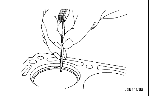
- Measure the piston ring end gap using the following procedure.
- Piston pin bores and pins must be free of varnish or scuffing.
- Place the piston ring (1) in the area of the bore where the piston ring will travel, approximately 25 mm below the deck surface. Ensure the ring is square with the cylinder bore by positioning the ring with the piston head.
- Measure the end gap of the piston ring with feeler gauges (2).
- If the clearance exceeds the provided specifications, the piston rings must be replaced.
- Repeat the procedure for all piston rings.
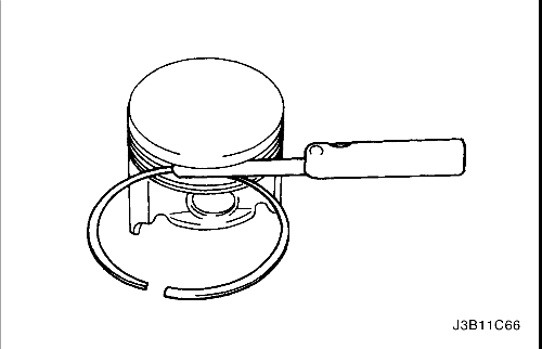
- Measure the piston ring side clearance using the following procedure.
- Roll the piston ring (1) entirely around the piston ring groove. If any binding is caused by the ring groove, dress the groove with a fine file. If any binding is caused by a distorted piston ring, replace the ring.
- With the piston ring on the piston, use feeler gauges (2) to check clearance at multiple locations.
- Compare the measurements with piston ring side clearance. Refer to "Engine Specifications" in this section.
- If the clearance is greater than specifications, replace the piston rings.
- If the new ring does not reduce the clearance to the correct specification, install a new piston.
- If the new piston does not meet clearance specifications, the cylinder block may need to be oversized to 0.25 mm. There is only one size of oversized pistons and rings available for service.

- Inspect the connecting rods for the following conditions.
- Inspect the connecting rod beam for twisting or bending.
- Inspect the rod cap for any nicks or damage caused by possible interference.
- Inspect for scratches or abrasion on the rod bearing seating surface.
- If the connecting rod bores contain minor scratches or abrasions, clean the bores in a circular direction with a light emery paper.
- Retain the original bolts for preliminary assembly. They must be replaced for final assembly.
- Measure the connecting rod piston pin bore to piston pin clearance using the following procedures.
- Using an outside micrometer (1), take two measurements of the piston pin (2) in the area of the connecting rod contact.

- Using an inside micrometer, measure the connecting rod piston pin bore (1).
- Subtract the piston pin diameter from the piston pin bore.
- Compare the clearance measurements. Refer to "Engine Specifications" in this section.
- If the clearance is excessive, replace the piston pin. If a new pin does not resolve the clearance problem, replace the connecting rod.

- Measure the connecting rod crankshaft bearing bore (1) using the following procedures.
- Using an inside micrometer, measure the connecting rod crankshaft bearing bore.
- Compare the bore measurements. Refer to "Engine Specifications" in this section.
- Replace the connecting rod if the bore is out of specification. Do not recondition the connecting rod.
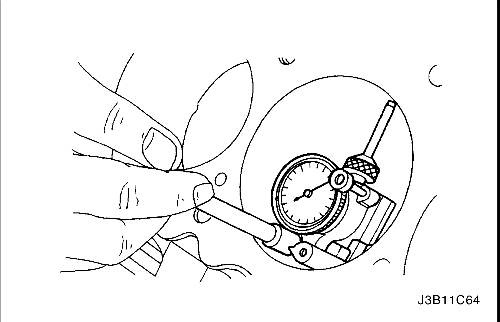
- Inspect the engine block deck surface for flatness using a straight edge and a feeler gauge. Refer to "Engine Specifications" in this section.
- Inspect the bearing bore for concentricity and alignment using cylinder bore check gauge J-8087. Refer to "Engine Specifications" in this section. If the bearing bore is beyond the specifications, replace the engine block.
- Inspect the engine block cylinder bore for wear, runout, ridging and taper using a bore gauge. Refer to "Engine Specifications" in this section.
- Inspect the engine block cylinder bore for glazing. Lightly hone the cylinder bore as necessary.
Installation Procedure
Important : For ease of installation of the piston pin, the connecting rod should be heated to 280°C. Heat the upper connecting rod only. Use commercial thermo color material to determine the correct temperature. When the thermo color material changes from black to green, the temperature is correct for installation.
- Align the notch on the piston and connecting rod so that the proper sides will be facing the front of the engine.
- Install the piston pin guide through the piston and the connecting rod.
- Coat the piston pin with clean oil.
- Install the piston pin into the opposite side of the piston.
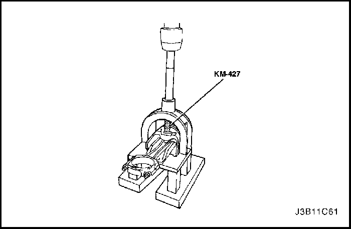
- Install the piston pin into the piston and connecting rod assembly using the piston pin service set KM-427.
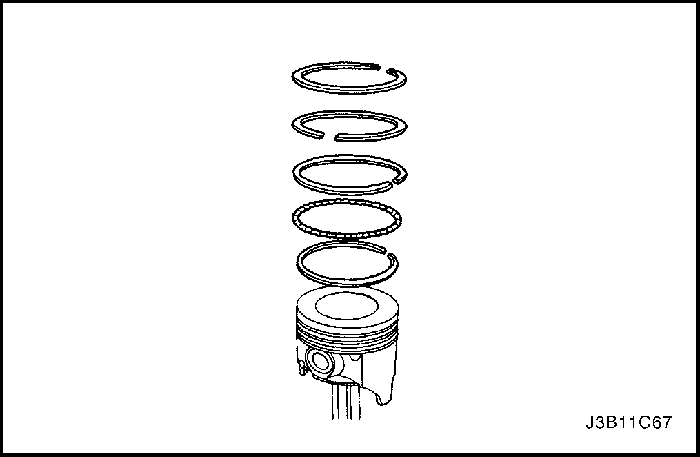
- Select a set of new piston rings.
- Install the piston oil ring, the expander, then the second piston oil ring to the bottom ring groove of the piston.
- Install the second compression ring to the middle ring groove of the piston.
- Install the top compression ring to the top ring groove of the piston.

- Use the piston ring expander to install the piston rings. Do not expand the piston rings beyond the expansion necessary for installation.
- Stagger the piston oil rings, the oil ring rail gaps, the second compression ring and the top compression ring in relation to the notch on the top of the piston.
- Lubricate the cylinder wall and the piston rings with clean engine oil.
- Install the piston using the universal piston ring compressor J-8037 and a wooden handle. Guide the lower connecting rod end to prevent damaging the crankshaft journal.
- Install the connecting rod cap and bearings. Refer to "Crankshaft Bearings and Connecting Rod Bearings - Gauging Plastic" in this section.
- Install the connecting rod cap bolts.
Tighten
Tighten the connecting rod bearing cap bolts to 35 N•m (26 lb-ft). Using the angular torque gauge KM-470-B, tighten the bolts one turn of 45 degrees plus on turn of 15 degrees.
- Install the crankshaft balancer unit assembly.
Tighten
Tighten the crankshaft balancer unit assembly bolts to 20 N•m (15 lb-ft) and turn the bolts another 45° using the angular torque gauge KM-470-B.
- Install the oil pan scraper bolts.
Tighten
Tighten the oil pan scraper bolts to 8 N•m (71 lb-in.).
- Install the oil suction pipe with the new O-ring.
Tighten
Tighten the oil suction pipe bolts to 8 N•m (71 lb-in.).
- Install the oil pan. Refer to "Oil Pan" in this section.
- Install the cylinder head with the intake manifold and exhaust manifold attached. Refer to "Cylinder Head and Gasket" "Cylinder Head and Gasket" in this section.
 | |  | |
| © Copyright Chevrolet Europe. All rights reserved |


