SECTION 1D1
ENGINE COOLING - 2.0 DIESEL
SPECIFICATIONS
Application | Description | Unit | Standard |
Cooling System | Cooling Type | - | PRESSURIZED TYPE |
Coolant | Coolant Capacity | L (qt) | 9 (9.51) |
Thermostat | Type | - | WAX PELLET |
Temperature (Opened initially) | °C (°F) | 80 ± 2 (176 ± 35.6) |
Temperature(perpectly opened) | °C (°F) | 95 (203) |
Temperature (Completely closed) | °C (°F) | 75 (167) or more |
Stroke(perpectly closed) | mm (in) | 8 (0.315) or more |
Cooling Fan | Type | - | ELECTRIC DUAL FAN |
Blade number(Main/Aux) | EA | 5 / 7 |
Cooling Fan Diameter(Main/Aux) | mm (in) | 340(13.39) / 320(12.60) |
Temperature at Low Speed ON | °C (°F) | 100 (212) |
Temperature at Low Speed OFF | °C (°F) | 97 (206.6) |
Temperature at High Speed ON | °C (°F) | 105 (221) |
Temperature at High Speed OFF | °C (°F) | 102 (215.6) |
Surge Tank | Open Pressure of the Pressure Valve | kPa/Psi | 137.3 (19.91) |
Open Pressure of the Vacuum Valve | kPa/Psi | 9.81 (1.42) |
Water Pump | Type | - | CENTRIFUGAL TYPE |
Impeller Diameter | mm (in) | 85 (3.35) |
Impeller blade Number | EA | 7 |
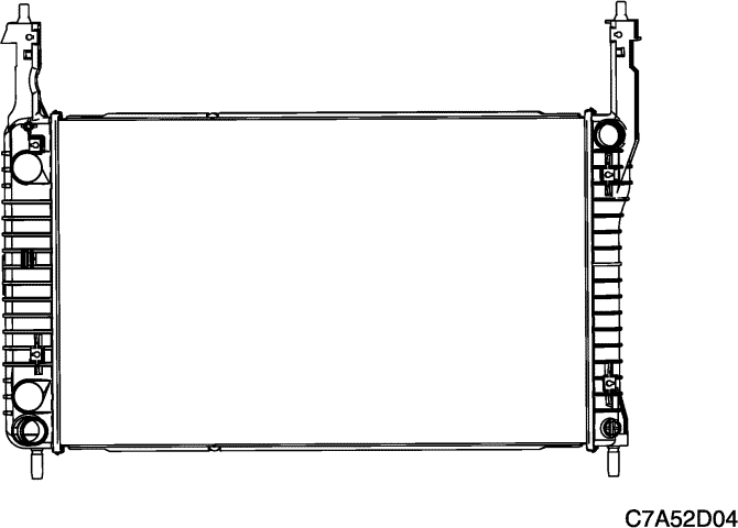
Radiator | Type | - | CROSS FLOW |
Core Width | mm (in) | 673 (26.50) |
Core Height | mm (in) | 414 (16.30) |
Core Depth | mm (in) | 27 (1.06) |
Fastener Tightening Specifications
Application | N•m | Lb-Ft | Lb-In |
A/C Condensor Retaining Bolt | 16 | 11.8 | - |
Cooling Fan Assembly Bolt | 4 | - | 35 |
Fan Blades Retaining Screw | 5.6 | - | 50 |
Fan Moter Retaining Screw | 3.5 | - | 31 |
Radiator Lower Bracket Bolt | 50 | 36.9 | - |
Radiator Upper Bracket Retaining Bolt | 20 | 14.8 | - |
Surge Tank Retaining Bolt and Nut | 8 | - | 71 |
Thermostat Housing Bolts | 23 | 17 | - |
Transaxle Oil Cooler and Line Retaining Bolt | 10 | - | 88.5 |
Water Pipe Retaining Bolt(M6) | 9 | - | 79.7 |
Water Pipe Retaining Bolt(M8) | 20 | 14.8 | - |
Water Pump Tightening Bolt | 11 | - | 97.4 |
COMPONENT LOCATOR
Radiator and Fan
- Radiator
- Charge Air Cooler
- Main Cooling Fan Blade
- Auxiliary Cooling Fan Blade
- Main Cooling Fan Motor
- Auxiliary Cooling Fan Motor
- Cooling Fan Shroud
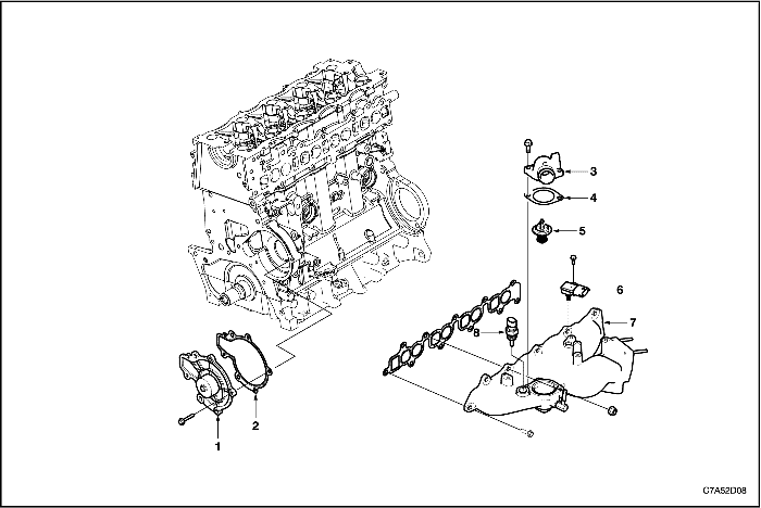
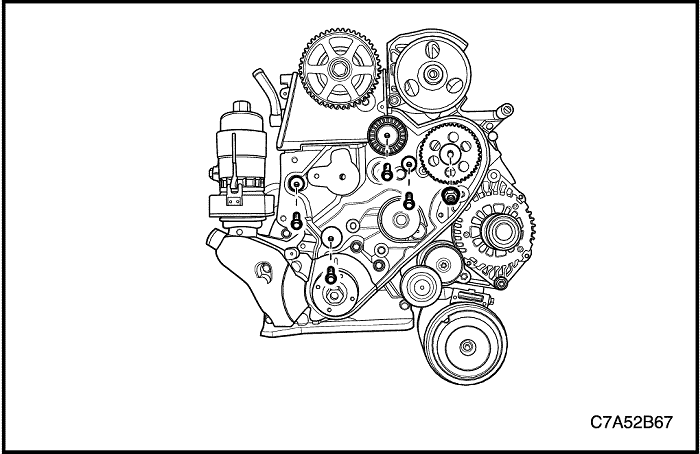
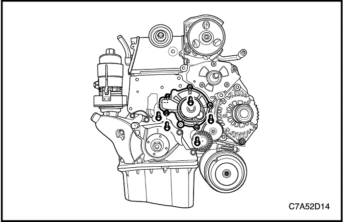
Water Pump and Thermostat
- Water Pump
- Water Pump Gasket
- Thermostat Housing
- Thermostat Gasket
- Thermostat
- T-MAP Sensor
- Coolant Temperature Sensor
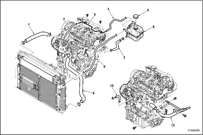
Cooling Path
- Radiator Upper Hose
- Thermostat By-Pass Hose
- Thermostat By-Pass Pipe
- Surge Tank – to- Thermostat By-Pass Hose
- Surge Tank Cap
- Surge Tank
- Surge Tank Hose
- Radiator – to – Surge Tank Return Hose
- Radiator Lower Hose
- Water Pump By-Pass Hose
- Water Pump Inlet Hose
- Water Pipe
DIAGNOSIS
Thermostat Test
- Remove the thermostat from the vehicle. Refer to "Thermostat" in this section.
- Make sure the valve spring is tight when the thermostat is fully closed. If the spring is not tight, replace the thermostat.
- Suspend the thermostat and a thermometer in a pan of 50/50 mixture of ethylene glycol and water. Do not let the thermostat or the thermometer rest on the bottom of the pan because the uneven concentration of heat on the bottom could result in inaccurate temperature measurements.
- Heat the pan on a burner.
- Use the thermometer to measure the temperature of the heated solution.
- The thermostat should begin to open at 87° (189°) and it should be fully open at 102° (216°). If it does not open at these temperatures, replace the thermostat.
Engine Overheats
Checks | Action |
Check for a loss of the coolant. | Add the coolant. |
Check for a weak coolant solution. | Confirm that the coolant solution is a 50/50 mixture of ethylene glycol and water. |
Check the front of the radiator for any dirt, any leaves, or any insects. | Clean the front of the radiator. |
Check for leakage from the hoses, the coolant pump, the heater, the thermostat housing, the radiator, the core plugs, or the head gasket. | Replace any damaged components. |
Check for a faulty thermostat. | Replace a damaged thermostat. |
Check for retarded ignition timing. | Perform an ECM code diagnosis. Confirm the integrity of the timing belt. |
Check for an improperly operating electric cooling fan. | Replace the electric cooling fan. |
Check for radiator hoses that are plugged or rotted. | Replace any damaged radiator hoses. |
Check for a faulty water pump. | Replace a faulty water pump. |
Check for a faulty surge tank cap. | Replace a faulty surge tank cap. |
Check for a cylinder head or an engine block that is cracked or plugged. | Repair the damaged cylinder head or the damaged engine block. |
Loss of Coolant
Checks | Action |
Check for a leak in the radiator. | Replace a damaged radiator. |
Check for a leak in the following locations: | Replace the following parts, as needed: |
Check for loose or damaged radiator hoses, heater hoses, and connections. | Reseat the hoses. Replace the hoses or the clamps. |
Check for leaks in the coolant pump seal. | Replace the coolant pump seal. |
Check for leaks in the coolant pump gasket. | Replace the coolant pump gasket. |
Check for an improper cylinder head torque. | Tighten the cylinder head bolts to specifications. Replace the cylinder head gasket, if needed. |
Check for leaks in the following locations: - Intake manifold.
- Cylinder head gasket.
- Cylinder block plug.
- Heater core.
- Radiator drain plug.
| Repair or replace any components, as needed, to correct the leak. |
Engine Fails to Reach Normal Operating Temperature or Cool Air from the Heater
Checks | Action |
Check to determine if the thermostat is stuck open or is the wrong type of thermostat. | Install a new thermostat of the correct type and heat range. |
Check the coolant level to determine if it is below the MIN mark on the surge tank. | Add sufficient coolant to raise the fluid to the specified mark on the surge tank. |
MAINTENANCE AND REPAIR
ON-VEHICLE SERVICE


Draining and Refilling the Cooling System
Caution : Do not remove the surge tank cap while the engine and the radiator are hot. Scalding fluid and steam may be blown out high pressure.
- Place a pan below the vehicle to catch the draining coolant.
- Remove the surge tank cap.
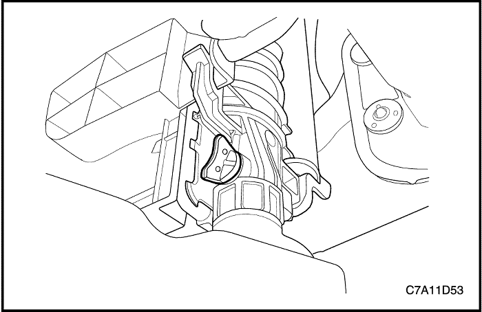
- Unplug the drain cock.
Caution : Dispose of the used coolant to a used coolant holding tank to be picked up with the used oil for disposal. Never pour the used coolant down the drain.
- Catch the escaping fluid in a drain pan.
- Remove all sludge and dirt from inside of the surge tank. Refer to "Surge Tank" in this section.
- Plug the drain cock.
- Add the clean water to the surge tank.
- Fill the tank slowly so that the upper reservoir hose remains above the water line. This allows the air inside the cooling system to escape.
- Start the engine.
- Run the engine until the thermostat opens. You can tell the thermostat is open when both radiator hoses are hot to the touch.

- Stop the engine.
- Repeat steps 1 through 9 until the drained water is clear and free of coolant and rust.
Notice : Never use an antifreeze mixture more concentrated than 60% antifreeze to 40% water. The solution freezing point increases above this concentration.
- Fill the cooling system through the surge tank with a mixture of Dex–cool and water. The mixture must be at least 50% antifreeze, but not more than 60% antifreeze.
- Fill the surge tank to the specified MAX fill mark on the outside of the tank.
Surge Tank
Removal Procedure
Caution : To prevent personal injury, do not remove the surge tank cap while the engine and the radiator are hot because the heat caused the system to remain under pressure. Scalding fluid and steam may be blown out high pressure.
- Drain the engine coolant to below the level of the surge tank.
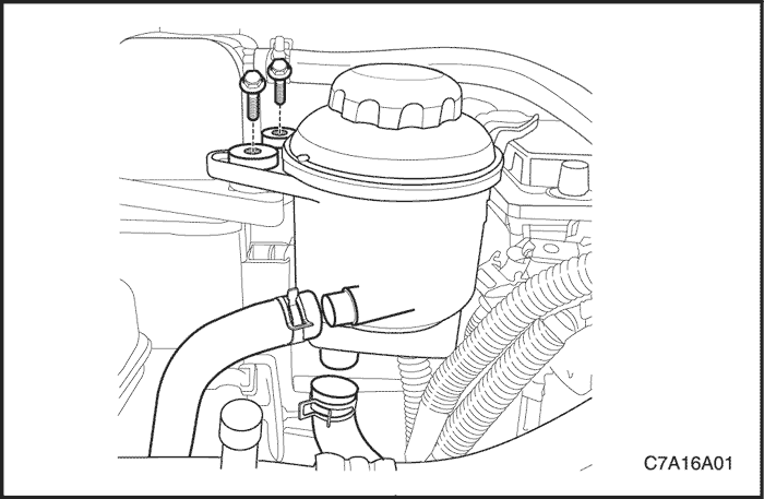
- Remove the power steering fluid reservoir. Refer to Section 6A, Power Steering System.

- Disconnect the return hose clamp and disconnect the return hose from the top of the surge tank.
- Disconnect the thermostat by-pass hose clamp and disconnect the thermostat by-pass hose from the top of the surge tank.
- Disconnect the feed hose clamp and disconnect the feed hose from the bottom of the surge tank.

- Remove the surge tank attaching bolt and nut.
- Remove the surge tank.
- Clean the inside and the outside of the surge tank and the surge tank cap with soap and water.
- Rinse the surge tank and the cap thoroughly.
Installation Procedure
- Install the surge tank.
- Secure the surge tank with the attaching bolt and nut.
Tighten
Tighten the surge tank retaining bolt and nuts to 8 N•m (71 lb-in.).
- Connect the return hose and the thermostat by-pass hose to the top of the surge tank.
- Connect the feed hose to the bottom of the surge tank.
- Fill the surge tank with the coolant to the center ridge or the MAX mark.
Electric Cooling Fan Assembly
Removal Procedure
- Disconnect the negative battery cable.
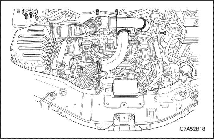
- Remove the beauty cover. Refer to Section 1B, Engine Mechanical-2.0 Diesel.
- Remove the charge air system hoses and ducts. Refer to Section 1B, Engine Mechanical-2.0 Diesel.
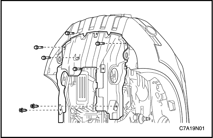
- Remove the engine undercover. Refer to Section 9N, Frame and Underbody.

- Tighten the radiator assembly to the upper bracket using by strings for not falling down.
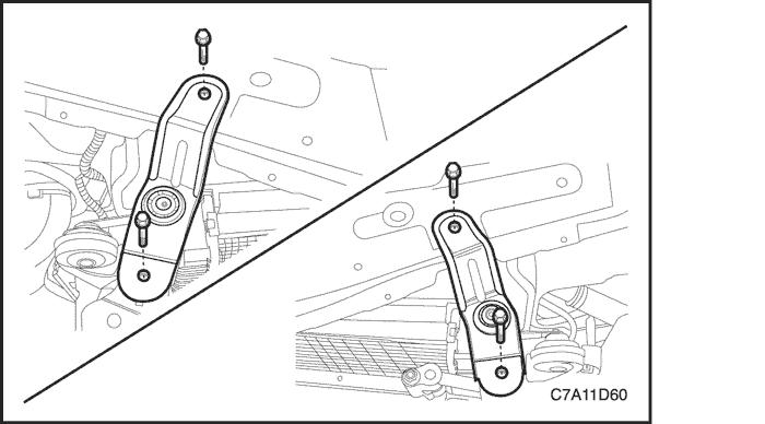
- Remove the radiator lower bracket from the cradle.

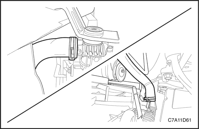
- Disconnect the both cooling fan electrical connectors.
- Remove the cooling fan shroud mounting bolts.
- Remove the cooling fan assembly downward.
- Remove the both main and auxiliary fan blades from the fan shroud assembly by removing the nut at the center of the fan hubs.
- Remove the both fan motor retaining screws.
- Remove the both fan motors from the shroud.
Installation Procedure
Caution : If a fan assembly is bent or damaged in any way, no attempt should be made to repair or reuse the damaged part. A bent or damaged fan assembly must be replaced with a new fan assembly. It is essential to remain the fan assemblies in proper balance. A fan assembly that is not in proper balance can fail and fly apart during use, creating extreme danger. Proper balance cannot be assured on a fan assembly that has been bent or damaged.
- Install the both fan motors to the shroud.
- Secure the motors to the shroud with the retaining screws.
Tighten
Tighten the fan motor retaining screws to 3.5 N•m (31 lb-in.).
- Install the fan blades to the fan shroud assembly with the nuts in the center of the fan hub.
Tighten
Tighten the fan blades retaining nuts to 5.6 N•m (50 lb-in.).
- Install the cooling fan assembly to the radiator.
Tighten
Tighten the cooling fan assembly bolts to 4 N•m (35 lb-in.).
- Install the radiator lower bracket to the cradle.
Tighten
Tighten the radiator lower bracket bolts to 50 N•m (39.6 lb-ft.).
Radiator
Removal Procedure
Caution : To prevent personal injury, do not remove the radiator while the engine and the radiator are hot.
- Remove the beauty cover. Refer to Section 1B, Engine Mechanical-2.0 Diesel.
- Remove the charge air cooler inlet/outlet hoses. Refer to Section 1B, Engine Mechanical-2.0 Diesel.
- Drain the engine coolant. Refer to "Draining and Refilling the Cooling System" in this section.
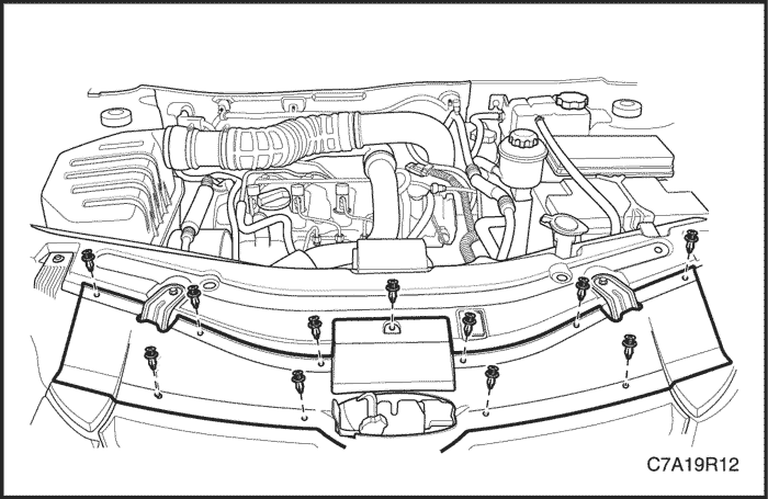
- Remove the radiator grill upper guide. Refer to Section 9R, Body Front End.
- Remove the engine undercover. Refer to Section 9N, Frame and Underbody.
- Discharge the A/C system, if equipped. Refer to Section 7B, Manual Control Heating, Ventilation, and Air Conditioning System.
- Remove the radiator upper bracket.
- Disconnect the transaxle oil cooler line from the automatic transaxle, if equipped. Refer to Section 5A, AISIN 55-51LE Automatic Transaxle.
- Disconnect the radiator upper/lower hoses from the radiator.
- Remove the A/C condenser inlet/outlet pipes from the A/C condenser, if equipped. Refer to Section 7B, Manual Control Heating, Ventilation, and Air Conditioning System.
- Remove the radiator lower bracket from the cradle.

Caution : Do not to damage the radiator fins for the proper operation of the cooling system.
- Carefully lower the radiator and fan assembly from the vehicle.
- Remove the radiator assembly.
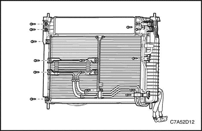
- Remove the transaxle oil cooler and line, if equipped.
- Remove the A/C condenser.
- Remove the charge air cooler.
Cleaning Procedure
Caution : NEVER spray water on a hot radiator. The resulting steam could cause personal injury.
Notice : The radiator fins are necessary for good heat transfer. Do not brush the fins. This may cause damage to the fins, reducing heat transfer.
Important : Remove bugs, leaves, dirt and other debris by blowing compressed air through the engine side of the radiator. Some conditions may require the use of warm water and a mild detergent.
- Clean the radiator cooling fins.
- Straighten any damaged cooling fins.
Installation Procedure
Caution : Do not to damage the radiator fins for the proper operation of the cooling system.
- Install the charge air cooler.
- Install the A/C condenser.
- Install the transaxle oil cooler and line, if equipped.
Tighten
- Tighten the charge air cooler retaining bolts to 8.5 N•m (75.2 lb-in).
- Tighten the A/C condenser retaining bolts to 16 N•m (11.8 lb-ft).
- Tighten the transaxle oil cooler and line retaining bolts to 10 N•m (88.5 lb-in).
- Install the radiator assembly.
- Install the radiator lower bracket to the cradle.
Tighten
Tighten the radiator lower bracket bolts and nuts to 50 N•m (36.9 lb-ft).
- Install the radiator upper bracket retaining bolts to 20 N•m (14.8 lb-ft).
Thermostat
Removal Procedure
Caution : To prevent personal injury, do not remove the surge tank cap while the engine and the radiator are hot because the heat caused the system to remain under pressure. Scalding fluid and steam may be blown out high pressure.
- Drain the coolant. Refer to "Draining and Refilling the Cooling System" in this section.
- Remove the beauty cover. Refer to Section 1B, Engine Mechanical-2.0 Diesel.
- Remove the charge air cooler inlet hose from the charge air cooler. Refer to Section 1B, Engine Mechanical-2.0 Diesel.
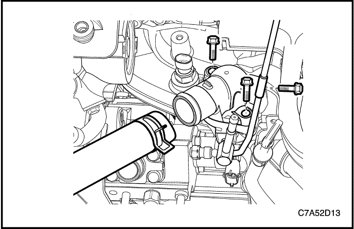
- Disconnect the radiator upper hose from the thermostat housing.
- Remove the fuel injection pump-to-rail feeding pipe retaining bolt.
- Remove the thermostat housing.
- Remove the thermostat with the gasket.
Installation Procedure
- Install the thermostat with a new gasket.
- Install the thermostat housing.
- Install the fuel pipe-to-common rail retaining bolt.
Tighten
- Tighten the thermostat housing bolts to 23 N•m (17 lb-ft).
- Tighten the fuel pipe-to-common rail retaining bolt to 10 N•m (88.5 lb-in).
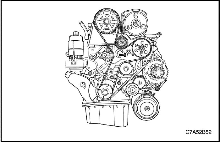
Water Pump
Removal Procedure
Caution : To prevent personal injury, do not remove the surge tank cap while the engine and the radiator are hot because the heat caused the system to remain under pressure. Scalding fluid and steam may be blown out high pressure.
- Drain the engine cooling system to a level below the thermostat housing. Refer to "Draining and Refilling the Cooling System" in this section.
- Remove the timing belt. Refer to Section 1B, Engine Mechanical-2.0 Diesel.
- Remove the timing belt idler.
- Remove the fuel injection pump sprocket.
- Remove the timing belt rear cover.
- Remove the water pump with the gasket.
Inspection Cleaning Procedure
- Inspect the water pump body for cracks and leaks.
- Inspect the water pump bearing for play or abnormal noise.
- Inspect the water pump pulley for excessive wear. If the water pump is defective, replace the water pump as a unit.
- Clean the mating surfaces of the water pump and the engine block.
Installation Procedure
- Install the water pump with a new gasket.
Tighten
Tighten the water pump tightening bolts to 11 N•m (97.4 lb-in).
- Install the timing belt idler.
- Install the fuel injection pump sprocket.
- Install the timing belt rear cover.
Tighten
- Tighten the timing belt idler bolt to 52 N•m (38.4 lb-ft).
- Tighten the injection pump sprocket nut to 70 N•m (51.6 lb-ft).
- Tighten the timing belt rear cover bolts to 11 N•m (97.4 lb-in).
GENERAL DESCRIPTION AND SYSTEM OPERATION
Cooling System
The cooling system's function is to maintain an efficient engine operating temperature during all engine speeds and operating conditions. The cooling system is designed to remove approximately one-third of the heat produced by the burning of the air-fuel mixture. When the engine is cold, the coolant does not flow to the radiator until the thermostat opens. This allows the engine to warm quickly.

- Water Pump
- Thermostat
- Radiator
- Main Cooling Fan
- Auxiliary Cooling Fan
- Intake Manifold
- Transaxle
- Water Pipe
- EGR Cooler
- Surge Tank
- Heater
- Engine Oil Cooler
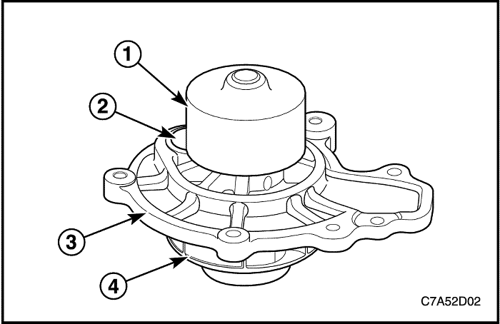
Water Pump
Water pump is a component of the engine cooling system and circulated the coolant from each cooling circuit components.
This water pump consists of sealing, bearing, pulley and housing and is driven by the crankshaft with the back of timing belt to loose noise to water pump pulley.
Water pump apply drain hole cup to cap to prevent coolant leakage for customers.
Water pump is not open impeller type but closed plastic impeller type to increase the cooling efficiency.
- Water Pump Pulley
- Drain Hole Cup Cap
- Housing
- Impeller
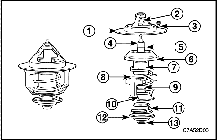
Thermostat
Thermostat controls coolant flowing and is assembled on the intake manifold. By coolant temperature, the wax-pellet of the thermostat expanded and shrunk mechanically main spring to flow the coolant.
The thermostat begins to open at 80°(176°) and fully open at 95°(203°). The thermostat closes at 75°(167°).
- Seat
- Cap
- Jiggle Valve
- Piston
- Stop Ring
- Rubber Valve
- Element Assembly
- Main Spring
- By-pass Shaft
- Frame
- By-pass Spring
- By-pass Valve
- Stop Ring
Radiator
The radiator is a heat exchanger. It consists of a core and two tanks. The aluminum core is a tube and fin cross-flow design that extends from the inlet tank to the outlet tank. Fins are placed around the outside of the tubes to improve heat transfer to the atmosphere.
The inlet and outlet tanks are a molded, high temperature, nylon reinforced plastic material. A high temperature rubber gasket seals the tank flange edge to the aluminum core. The tanks are clamped to the core with clinch tabs. The tabs are part of the aluminum header at each end of the core.
The radiator also has a drain cock located in the bottom of the left hand tank. The drain cock unit includes the drain cock and drain cock seal.
The radiator removes heat from the coolant passing through it. The fins on the core transfer heat from the coolant passing through the tubes. As air passes between the fins, it absorbs heat and cools the coolant.
Surge Tank
The surge tank is a plastic tank with a threaded pressure cap. The tank is mounted at a point higher than all other coolant passages. The surge tank provides an air space in the cooling system that allows the coolant to expand and contract. The surge tank provides a coolant fill point and a central air bleed location.
During vehicle use, the coolant heats and expands. The increased coolant volume flows into the surge tank. As the coolant circulates, any air is allowed to bubble out. Coolant without air bubbles absorbs heat much better than coolant with bubbles.

Cooling Fan
The cooling fans are mounted behind the radiator in the engine compartment. The engine cooling fan is driven by electric power. The cooling fan draws air through the radiator to improve the transfer of heat from the coolant to the atmosphere. As the fan blades spin, they increase the flow of air across the radiator core and across the condenser on air condition (A/C)–equipped vehicles. This helps to speed cooling when the vehicle is at idle or moving at low speeds.