SECTION 1G3
ENGINE EXHAUST - HFV6 3.2L
SPECIFICATIONS
Fastener Tightening Specifications
Application | N•m | Lb-Ft | Lb-In |
Pup Converter Upper Flange Nuts | 40 | 30 | - |
Pup Converter to Exhaust Front Pipe Nuts | 40 | 30 | - |
Exhaust Front Pipe Support Bracket Bolt | 40 | 30 | - |
Exhaust Front Pipe to Underbody Catalytic Converter Nuts | 30 | 22 | - |
Underbody Catalytic Converter to Front Muffler Nuts | 30 | 22 | - |
Front Muffler to Rear Muffler Nuts | 40 | 30 | - |
Exhaust Manifold Heat Shield Bolts | 15 | 11 | - |
Underbody Catalytic Converter Heat Shield Nuts | 2.5 | - | 22 |
Front Muffler Heat Shield Nuts | 2.5 | - | 22 |
Rear Muffler Heat Shield Nuts | 2.5 | - | 22 |
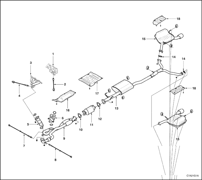
COMPONENT LOCATOR
- Exhaust Manifold, Bank 1
- Upper Heated Oxygen Sensor, Bank 1
- Exhaust Manifold, Bank 2
- Upper Heated Oxygen Sensor, Bank 2
- Pup Converter, Bank 2
- Pup Converter, Bank 1
- Lower Heated Oxygen Sensor, Bank1
- Lower Heated Oxygen Sensor, Bank 2
- Exhaust Front Pipe
- Exhaust Front Pipe to UCC Gasket
- Underbody Catalytic Converter (UCC)
- UCC to Front Muffler Gasket
- Front Muffler Assembly
- Front Muffler to Rear Muffler Gasket
- Rear Muffler Assembly
- UCC Heat Shield
- Front Muffler Heat Shield
- Rear Muffler Heat Shields
Exhaust System Diagnosis
Condition | Probable Cause | Correction |
Leaking exhaust gases | Leaks at pipe joints. | Tighten nuts and bolts to the specified torques. |
Damaged or improperly installed converter sealing ring/gaskets. | Replace sealing ring/gasket as necessary. |
Burned or rusted out exhaust pipe or muffler/s. | Replace component as necessary. |
Exhaust noises | Leaks at manifold or pipe connections. | Tighten bolts/nuts at leaking connections to specified torques. Replace gasket as required. |
Burned or blown out pipe or muffler/s. | Replace pipe/muffler assembly as necessary. |
Exhaust manifold/s cracked or broken. | Replace manifold. |
Leak between manifold/s and cylinder head/s. | Tighten manifold to cylinder head studs to specified torque. |
Loss of engine power, hesitation, surging, poor fuel economy, stalling or hard starting | Clogged catalytic converter (may result from serious engine malfunction). | Replace catalytic converter. |
Crushed pipe work. | Replace pipe work. |
Internal rattling in muffler | Dislodged tubes and/or baffles in muffler. | Replace muffler. |
Catalytic converter has crumbled and pieces blown into muffler. | Replace catalytic converter assembly and affected muffler. |
Rattling or knocking exhaust system | Damaged, worn, missing or improperly installed support rubber hangers. | Check and replace as necessary. |
Damaged mounting hangers or pegs. | Service / replace hangers or pegs as necessary. |
Improper alignment. | Tighten all fasteners according to tightening sequence and the specified torques. |
Damaged or incorrect exhaust system components. | Replace damaged or incorrect components as necessary. |
MAINTENANCE AND REPAIR
ON-VEHICLE SERVICE


Pup Converter
Removal Procedure
- Disconnect the negative battery cable.
- Remove the exhaust front pipe. Refer to "Exhaust Front Pipe" in this section.
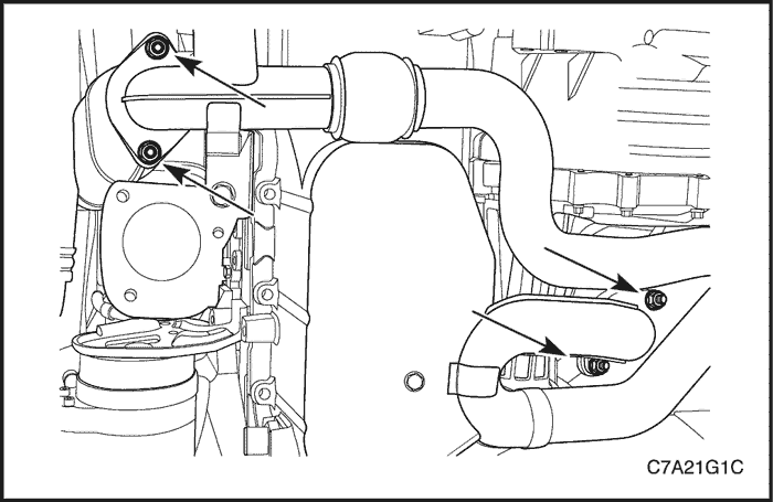
- Remove the bank 2 pup converter upper flange-to-bank 2 exhaust manifold retaining nuts, 3 places.
Important : The nuts and the stud may unscrew as a unit because of the high temperature associated with the exhaust manifold, but they can be reused as such.
- Remove the bank 2 pup converter and gasket.
- Remove the bank 1 pup converter upper flange-to-bank 1 exhaust manifold retaining nuts, 2 places.
Important : The nuts and the stud may unscrew as a unit because of the high temperature associated with the exhaust manifold, but they can be reused as such.
- Remove the bank 1 pup converter and gasket.
- Clean the sealing surfaces on the exhaust front pipe and the both exhaust manifolds.
- Check the exhaust front pipe and the both exhaust manifolds for holes, damage, open seams or other deterioration which could permit exhaust fumes to seep into the passenger compartment.
Installation Procedure
- Install the gasket and the bank 2 pup converter upper flange-to-bank 2 exhaust manifold retaining nuts, 3 places.
Tighten
Tighten the bank 2 pup converter upper flange nuts to 40 N•m (30 lb-ft).
- Install the gasket and the bank 1 pup converter upper flange-to-bank 1 exhaust manifold retaining nuts, 2 places.
Tighten
Tighten the bank 1 pup converter upper flange nuts to 40 N•m (30 lb-ft).
- Install the exhaust front pipe. Refer to "Exhaust Front Pipe" in this section.
Tighten
Tighten the pup converter-to-exhaust front pipe retaining nuts to 40 N•m (30 lb-ft).
Exhaust Front Pipe
Removal Procedure
- Disconnect the negative battery cable.
- Remove the engine under cover.
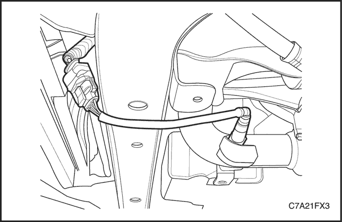
- Disconnect the lower heated oxygen sensor connector (BANK 2).
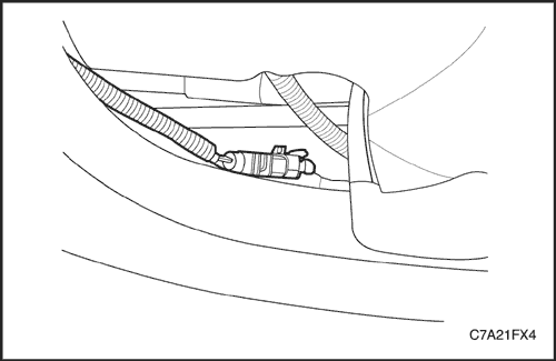
- Disconnect the lower heated oxygen sensor connector (BANK 1).

- Remove the exhaust front pipe support bracket retaining bolts from the oil pan.
- Remove the pup converter-to-exhaust front pipe retaining nuts at the BANK 1 and BANK 2.
- Remove the pup converter-to-exhaust front pipe gasket.

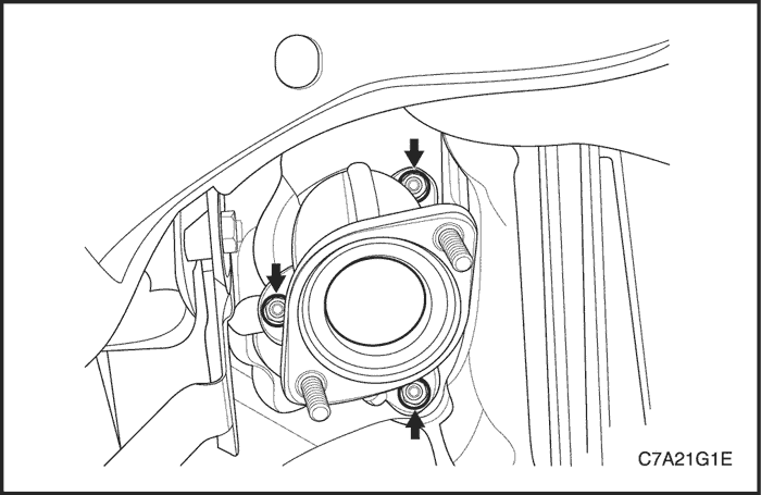
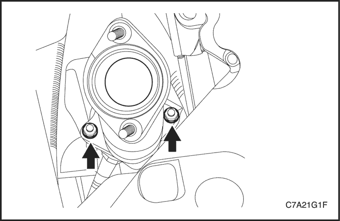
- Remove the nuts (3 places) from the exhaust front pipe-to underbody catalytic converter (UCC).
- Remove the exhaust front pipe-to-UCC gasket.
- Remove the exhaust front pipe.
- Clean the sealing surfaces on the UCC flange and the exhaust front pipe.
- Check the exhaust front pipe for holes, damage, open seams or other deterioration which could permit exhaust fumes to seep into the passenger compartment.
Installation Procedure
- Install the the exhaust front pipe-to-UCC retaining nuts (3 places) and gasket.
Tighten
Tighten the exhaust front pipe-to-underbody catalytic converter retaining nuts to 30 N•m (22 lb-ft).
- Install the pup converter-to-exhaust front pipe flange nuts with the gaskets at the BANK 1 and BANK 2.
Tighten
Tighten the pup converter-to-exhaust front pipe retaining nuts to 40 N•m (30 lb-ft).
- Install the exhaust front pipe support bracket bolts to the oil pan.
Tighten
Tighten the exhaust front pipe support bracket retaining bolts to 40 N•m (30 lb-ft).
- Connect the lower heated oxygen sensor connectors.
- Install the engine under cover.
- Connect the negative battery cable.
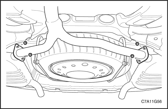
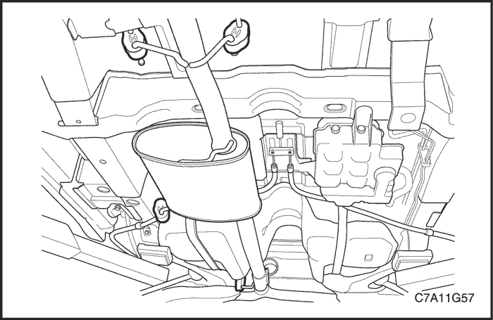
Underbody Catalytic Converter (UCC)
Removal Procedure
- Remove the nuts (3 places) and gasket from the exhaust front pipe-to-underbody catalytic converter (UCC).

- Remove the nuts and gasket from the UCC-to-front muffler pipe.
- Remove the UCC assembly.
Installation Procedure
- Install the nuts and gasket to the UCC-to-front muffler pipe.
Tighten
Tighten the underbody catalytic converter-to-front muffler nuts to 30 N•m (22 lb-ft).
- Install the nuts (3 places) and gasket to the exhaust front pipe-to- UCC.
Tighten
Tighten the exhaust front pipe-to-underbody catalytic converter nuts to 30 N•m (22 lb-ft).
Front Muffler
Removal Procedure
- Remove the nuts and the gasket from the front muffler pipe-to-underbody catalytic converter (UCC).
- Remove the nuts and the gaskets from the both rear muffler pipe flange.
- Disconnect the front muffler from the rubber hangers.
- Remove the front muffler.
- Check the UCC and the front muffler for holes, damage, open seams or other deterioration which could permit exhaust fumes to seep into the passenger compartment or the trunk.
Installation Procedure
- Secure the front muffler to the rubber hangers.
- Install the nuts and the gaskets to the both rear muffler pipe flange.
Tighten
Tighten the front muffler-to-rear muffler nuts to 40 N•m (30 lb-ft).
- Install the nuts and gasket to the front muffler pipe-to-UCC.
Tighten
Tighten the front muffler-to-underbody catalytic converter nuts to 30 N•m (22 lb-ft).
Rear Muffler
Removal Procedure
- Remove the nuts and the gaskets from the both rear muffler pipe flange-to-front muffler pipe flange.

- Detach the both rear muffler assembly from the rubber hangers.
- Remove the both rear muffler.
- Check the rear muffler and the pipe for holes, damage, open seams and other deterioration which could permit exhaust fumes to seep into the passenger compartment or the trunk.
Installation Procedure
- Secure the both rear muffler assembly to the rubber hangers.
- Install the nuts and the gaskets to the both rear muffler pipe flange-to-front muffler pipe flange.
Tighten
Tighten the front muffler-to-rear muffler nuts to 40 N•m (30 lb-ft).
GENERAL DESCRIPTION AND SYSTEM OPERATION
Exhaust System
Notice : When you are inspecting or replacing the exhaust system components, make sure there is adequate clearance from all points on the underbody to avoid possible overheating of the floor pan and possible damage to the passenger compartment insulation and trim materials.
Caution : Check the complete exhaust system and the nearby body areas and the trunk lid for broken, damaged, missing, or mispositioned parts, open seams, holes, loose connections, or other deterioration which could permit hazardous exhaust fumes to seep into the trunk or the passenger compartment. Dust or water in the trunk may be an indication of a problem in one of these areas. Any defects should be corrected immediately.
Muffler
If holes, open seams or any deterioration is discovered upon inspection of the front muffler and pipe assembly, the complete assembly should be replaced. The same procedure is applicable to the rear muffler assembly. Heat shields in the front and the rear muffler assembly positions, as well as for the catalytic converter and the connecting pipe, protect the vehicle and the environment from high temperatures the exhaust system develops.
Catalytic Converters (Pup Converter)
The catalytic converter is a substance that accelerates a chemical reaction without itself being changed. Engine exhaust gases contain carbon monoxide (CO), hydrocarbons (HC) and oxides of nitrogen (NOx). When the exhaust gases flow through the monolith, reactions with the catalytic converter occur. CO and HC are converted by oxidation with oxygen (O2) in the exhaust gases to produce carbon dioxide (CO2) and water vapour (H2O). NOx is converted by reduction with CO to produce nitrogen (N2) and CO2. The converter is called a three-way type because it simultaneously converts three components of exhaust gas (CO, HC and NOx) to harmless natural gases.
Catalytic converter can be damaged or rendered ineffective, if: the engine burns excessive amount of oil or the exhaust temperature at the converter is too high (exceeds 840°C).
Notice : The catalytic converter requires the use of unleaded fuel only, or damage to the catalyst will result.
The catalytic material is very sensitive to the effects of a rich or lean fuel mixture, which may cause the temperature of the converter to rise rapidly. The catalytic converter normally operates at approximately 600°C.
The catalytic converter is also sensitive to the use of leaded petrol. Using leaded fuel can cause deposits to form in the converter, which restrict exhaust flow and prevent the catalyst from working. This will result in an increase in exhaust backpressure and converter temperature.