SECTION 4F
ANTILOCK BRAKE SYSTEM
Caution : Disconnect the negative battery cable before removing or installing any electrical unit or when atool or equipment could easily come in contact with exposed electrical terminals. Disconnecting this cablewill help prevent personal injury and damage to the vehicle. The ignition must also be in LOCK unlessotherwise noted.
SPECIFICATIONS
General Specifications
Application | Unit | Description |
ABS Mode | - | 4 Channel 4 Sensor |
Hydraulic Modulator | Operation Voltage | V | 10 - 16 |
Motor Revolutions | rpm | 5000 Max. |
Main Relay | Location | - | Inside of EBCM |
Operation Voltage | V | 10 - 16 |
Wheel Speed Sensor | Sensor Operation Voltage | V | 7.5 - 20 |
Signal Frequency Range | kHz | 0 - 2.0 |
Brake Oil | Type | - | DOT - 4 |
Capacity | Liter | 0.67 |
Fastener Tightening Specifications
Application | N•m | Lb-Ft | Lb-In |
Brake Pipe Fitting Nut (Hydraulic Unit) | 16 | 12 | - |
ABS Module Mounting Bracket Bolt | 10 | - | 89 |
EBCM to BPMV Screws | 3 | - | 27 |
Damping Bolts to Brake Modulator Assembly | 11 | 8 | - |
Wheel Speed Sensor to Hub Bolt | 8 | - | 71 |
SCHEMATIC AND ROUTING DIAGRAMS
Abs System Circuit (I)
Abs System Circuit (II)
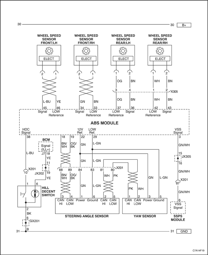
Electrical Schematic (I) - ABS
Electrical Schematic (II) - ABS with ESP (Electronic Stability Program)
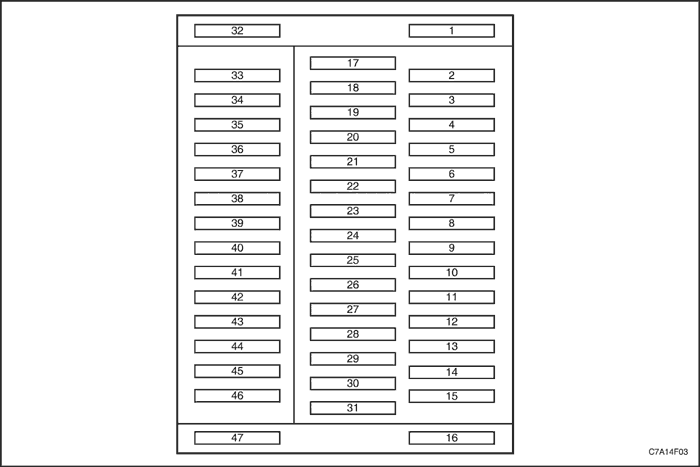
EBCM Harness Connector end View and Pin Layout
ABS (With ESP) Pin Assignments
Pin Number | Circuit Function |
1 | Battery (Hydraulic Motor) |
2 | - |
3 | VSS (Vehicle Steering Sensor) Signal from SSPS Module |
4 | - |
5 | - |
6 | - |
7 | - |
8 | Communication Enable (BCM & AWD Control Module) |
9 | - |
10 | - |
11 | MainGMLAN - High Out (CAN - High) |
12 | MainGMLAN - High In (CAN - High) |
13 | MainGMLAN - High In (CAN - Low) |
14 | MainGMLAN - High Out (CAN - Low) |
15 | - |
16 | Ground |
17 | - |
18 | Yaw Sensor CAN - High |
19 | Yaw Sensor CAN - Low |
20 | - |
21 | - |
22 | Yaw Sensor Power Supply (Reference - 12 V) |
23 | - |
24 | - |
25 | - |
26 | - |
27 | - |
28 | - |
29 | Yaw Sensor (Low Reference - Ground) |
30 | - |
31 | - |
32 | Battery (Electronics & Valves) |
33 | Wheel Speed Sensor - Front Right (Low Reference - Ground) |
34 | Wheel Speed Sensor - Front Right (Signal) |
35 | - |
36 | Wheel Speed Sensor - Rear Left (Signal) |
37 | Wheel Speed Sensor - Rear Left (Low Reference - Ground) |
38 | HCD (Hill Descent Control) Signal |
39 | - |
40 | - |
41 | - |
42 | Wheel Speed Sensor - Rear Right (Low Reference - Ground) |
43 | Wheel Speed Sensor - Rear Right (Signal) |
44 | - |
45 | Wheel Speed Sensor - Front Left (Signal) |
46 | Wheel Speed Sensor - Front Left (Low Reference - Ground) |
47 | - |
Hydraulic Diagram
COMPONENT LOCATOR
ABS System
- Hydraulic Electronic Control Unit
- Front Wheel Speed Sensor
- Rear Wheel Speed Sensor
DIAGNOSIS
Diagnostic Trouble Code and Description
DTC | Decsription |
C0035 | Left Front Wheel Speed Sensor Circuit |
C0040 | Right Front Wheel Speed Sensor Circuit |
C0045 | Left Rear Wheel Speed Sensor Circuit |
C0050 | Right Rear Wheel Speed Sensor Circuit |
C0110 | Pump Motor Circuit |
C0131 | Antilock Brake System (ABS)/Traction Control System (TCS) Pressure Circuit |
C0161 | Antilock Brake System (ABS)/Traction Control System (TCS) Brake Switch / Sensor Circuit |
C0186 | Lateral Accelerometer Circuit |
C0196 | Yaw Rate Circuit |
C0252 | Vehicle Stability Enhancement System (VSES) Sensors Uncorrelated |
C0280 | Stability System Active Too Long |
C0287 | Longitudinal Accelerometer Circuit |
C0292 | VSES Combination Sensor Circuits |
C0460 | Steering Position Sensor |
C0550 | Electronic Control Unit (ECU) Performance |
C0551 | Option Configuration Error |
C0561 | System Disabled Information Stored |
C0569 | System Configuration Error |
C0899 | Device {single or 1} Voltage Low |
C0900 | Device {single or 1} Voltage High |
U0102 | Lost Communication with RDM (Transfer Case Module) |
U1500 | CAN 2 (Sensor Cluster) Bus Communication Malfunction (Bus Off) |
U2100 | CAN Bus Communication Malfunction (Bus Off) |
U2105 | Lost Communication with ECM |
U2106 | Lost Communication with TCM |
U2107 | Lost Communication with BCM |
U2139 | Lost Communication with Gateway Module |
U2142 | Lost Communication with Sensor Cluster |
U2143 | Lost Communication with Steering Wheel Angle Sensor |
Diagnostic Circuit Check
System Description
The Diagnostic Circuit Check is an organized method of identifying any problems caused by a malfunction in the ABS/DDRP system.
A service technician should begin diagnosis of any ABS/DDRP complaint with the Diagnostic Circuit Check. The Diagnostic Circuit Check directs a service technician to the next logical step when diagnosing a complaint.
Serial Data is transmitted/received by the EBCM through terminal 11 and 14. The EBCM is supplied with constant battery feed voltage through terminals 1 and 32, and switched ignition voltage through terminal 4. The EBCM ground is provided through terminal 16.
Diagnostic Process
Use the following ordered procedure when servicing the ABS/DDRP system.
- Inspect the vehicle for any mechanical conditions related the brake system.
- Brake reservoir fluid level correct.
- Inspect master for fluid for contamination.
- Inspect brake master/modulator for leaks.
- Inspect brake master/modulator for leaks.
- Inspect brake components at all wheels.
- Verify no brake drag exists (brake switch adjustment).
- Verify even brake apply (no pull or lead).
- Inspect for worn/damaged brake pads.
- Inspect for worn/damaged wheel bearings
- Inspect wheel speed sensors/wiring.
- Inspect exciter rings for damage
- Inspect tires for tread depth/wear.
- Road test the vehicle to verify the complaint
- Perform the Diagnostic Circuit Check and proceed to the applicable Diagnostic Trouble Chart as necessary.
- Clear the ABS DTCs (Diagnostic Trouble Codes) after all of the system malfunctions have been corrected.
Diagnostic Circuit Check
| Step | Action | Value(s) | Yes | No |
| 1 | - Connect or install all previously disconnected or removed components if applicable.
- Ignition switch "ON"
- Install the applicable Scan Tool into the DLC and attempt to communicate with the EBCM.
Does the Scan Tool communicate with the EBCM? | - | Go to Step 2 | Go to Step 4 |
| 2 | Were any DTC(s) stored current or history? | - | Go to Step 3 | Go to Step 7 |
| 3 | - Document Current DTC(s).
- Document History DTC(s).
- Document Enhanced History Data such as
- number of times each DTC set.
- number of times since each DTC first set.
- number of times each DTC set.
- speed when each DTC set.
- other Enhanced Data which may assist with diagnosis.
- Do not clear DTC(s) prior to fully documenting the information from the scan tool.
- Refer to the applicable Diagnostic Trouble Code(s). Refer to "Diagnostic Trouble Code and Description" in this section.
| - | - | - |
| 4 | Check the DLC wiring harness, battery and cable. Is all the conditions OK? | - | Go to Step 5 | Go to Step 6 |
| 5 | - Replace the EBCM with new one.
- Check the new EBCM with the scan tool.
Did you find any DTC? | - | Go to Step 1 | System OK |
| 6 | - Repair the DLC harness or battery cable.
- Replace the DLC harness or battery cable or battery as needed.
- Check the EBCM with the scan tool.
Did you find any DTC? | - | Go to Step 1 | System OK |
| 7 | - Ignition switch "OFF"
- Wait 10 seconds.
- Ignition switch "ON"
- Observe the amber ABS lamp when the key is turned on.
Did the ABS Warning Lamp and Brake Warning Lamp turn on for 3 seconds and then turn off? (bulb test) | - | Go to Step 8 | Go to Step 9 |
| 8 | System functioning as designed. | - | System OK | - |
| 9 | Did the any lamp stay on? | - | Go to Step 10 | System OK |
| 10 | Go to appropriate DTC trouble table. | - | - | - |
Diagnostic Test Drive
When servicing vehicles, the vehicle antilock brake system (ABS) and traction control system (TCS), test drives will be necessary to allow all tests to be run, and all system functions to be enabled and exercised. A test drive may also be required to duplicate specific DTCs covered in this section. The diagnostic system check (including test drive) should be run when vehicle repairs are complete in order to verify the repair.
The diagnostic test drive will vary for ABS/TCS problems.
- Read the Diagnostic Aids and the Conditions for Setting the DTC.
- Reconnect any previously disconnected components.
- Start the engine.
- Drive the vehicle under the following conditions for at least 10 minutes. At no times should any unlawful or unsafe maneuvers be performed.
- Highway driving
- Rough roads
- Verify the customer’s concern and duplicate driving conditions.
- With the engine still running, use the scan tool and check for any DTCs. If any DTCs are set, perform the appropriate DTC table.
Initialization Sequence
The electronic brake control module (ECBM) performs the initialization test once each ignition cycle, when the vehicle speed reaches 15 km/h (9 mph). The initialization sequence cycles each valve solenoid and the pump motor, as well as the necessary relays, to check component operation. If any error is detected, the EBCM will set a DTC. The initialization sequence may be heard and felt while it is taking place, and is considered part of normal operation.