MAINTENANCE AND REPAIR
ON-VEHICLE SERVICE
Service Precautions
Caution : Brake fluid may irritate eyes and skin. In case of contact, take the following actions:
- Eye contact - rinse thoroughly with water.
- Skin contact - wash with soap and water.
- Ingestion - consult a physician immediately.
Notice : When fasteners are removed, always reinstall them at the same location from which they were removed. If a fastener needs to be replaced, use the correct part number fastener for that application. If the correct part number fastener is not available, a fastener of equal size and strength (or stronger) may be used. Fasteners that are not reused and those requiring thread-locking compound will be called out. The correct torque values must be used when installing fasteners that require them. If the above procedures are not followed parts or system damage could result.
Notice : Use only or DOT-4 hydraulic brake fluid. When you do need brake fluid, use proper fluid written on the brake fluid cap. The use of DOT 5 (silicone) brake fluid is not recommended. Otherwise, reduced brake performance or durability may result.
Notice : Avoid spilling brake fluid on any of the vehicle's painted surface, wiring cables, or electrical connectors. Brake fluid will damage paint and electrical connectors. If any fluid is spilling on the vehicle, flush the area with water to lessen the damage.
Bleeding System
Replacement modulators are shipped already filled and bled. In normal procedures requiring removal of the modulator, such as to replace the HECU, air will not enter the modulator, and normal bleeding will be all that is needed. For this procedure, refer to
Section 4A, Hydraulic Brakes.


Electronic Brake Control Module
Removal Procedure
- Turn the ignition switch to the OFF position.
- Remove the engine coolant reservior tank and fuse box. Refer to Section 1D2, Engine Cooling (FAM II 2.4 D) and Section 1E2 Engine Electrical (FAM II 2.4 D).
- Clean the electronic brake control module (EBCM) to brake pressure modulator valve (BPMV) area of any accumulated dirt and foreign material.
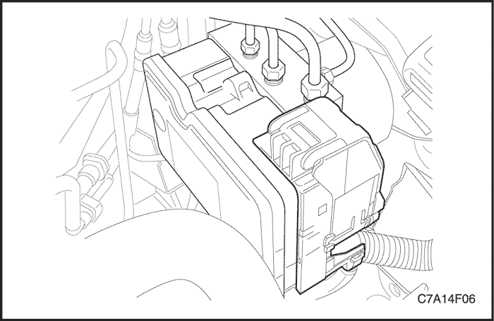
- Disconnect the electrical connector from the EBCM.
- Remove the EBCM attaching screws.
- Separate the EBCM from the BPMV by carefully pulling apart.
Installation Procedure
- Clean the sealing surface of the BPMV, with denatured alcohol and a clean shop cloth.
- Install the EBCM to the BPMV.
- Install the EBCM-to-BPMV attaching screws. Tighten the screws in a cross pattern.
Tighten
Tighten the screws to 3 N•m (27 lb-in).
- Connect the electrical connector to the EBCM.
- Install the engine coolant resevior tank and fuse box. Refer to Section 1D2, Engine Cooling (FAM II 2.4 D) and Section 1E2 Engine Electrical (FAM II 2.4 D).
- Turn the ignition switch to the ON position. DO NOT start the engine.
- Perform the steering angle sensor centering using scan tool. Refer to Section 6E, Steering Wheel and Column.
- Perform the Diagnostic Circuit Check.
Brake Modulator Assembly
Caution : Brake fluid may irritate eyes skin. Incase of contact, take the following actions :
- Eye contact - rinse thoroughly with water.
- Skin contact - wash with soap and water.
- If ingested - consult a physician immediately.
Notice : Avoid spilling connections, wiring, or cables. Brake fluid will damage painted surfaces and cause corrosion to electrical components. If any brake fluid comes in contact with painted surfaces, immediately flush the area with water. If any brake fluid comes in contact with electrical connections, wiring, or cables, use a clean shop cloth to wipe away the fluid.
Removal Procedure
- Turn the ignition switch to the OFF position.
- Remove the engine coolant reservior tank and fuse box. Refer to Section 1D2, Engine Cooling (FAM II 2.4 D) and Section 1E2 Engine Electrical (FAM II 2.4 D).
- Clean the brake modulator assembly pipe fitting areas of any accumulated dirt and foreign material.
- Disconnect the electrical connector from the electronic brake control module (EBCM).
- Place a shop towel under the brake modulator assembly to catch any brake fluid loss.
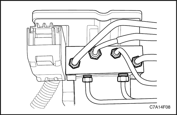
Important : Prior to disconnecting the brake pipes from the antilock brake system (ABS) modulator assembly, note the locations of the brake pipes to the valve assembly, to aid during installation.
- Disconnect the brake pipe fitting nuts from the brake pressure modulator valve (BPMV).
- Cap the brake pipe ends to prevent brake fluid loss and contamination.
- Plug the modulator brake pipe openings to prevent brake fluid loss and contamination.
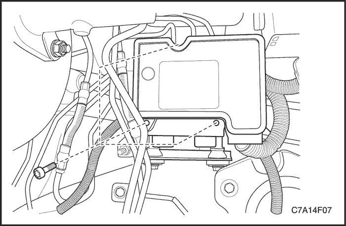
- Remove the mounting bracket bolt and nuts from the body panel.
- Remove the brake modulator assembly to the mounting backet damping bolts.
Installation Procedure
- Install the damping bolts to the brake modulator assembly.
Tighten
Tighten the damping bolts to the brake modulator assembly to 11 N•m (8 lb-ft).
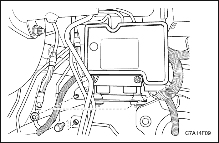
- Install the brake modulator assembly to the modulator bracket.
- Install the brake modulator assembly with the mounting bracket attached to the body panel.
Tighten
Tighten the mounting bracket bolt and nuts to 10 N•m (89 lb-in).
- Remove the caps from the master cylinder brake pipe ends.
- Remove the plugs from the master cylinder ports on the modulator assembly.
- Connect the master cylinder brake pipes to the modulator assembly, in the same location as removed.
- Tighten the brake pipe fittings nuts.
Tighten
Tighten the fitting nuts to 16 N•m (12 lb-ft).
- Connect the electrical connector to the EBCM.
- Install the engine coolant reservior tank and fuse box.
- Bleed the hydraulic brake system. Refer to Section 4A, Hydrautic Brakes.
- Turn the ignition switch to the ON position. DO NOT start engine.
- Perform the Diagnostic Circuit Check in this section.
Front Wheel Speed Sensor
Removal Procedure
- Raise and support the vehicle.
- Remove the tire and wheel assembly.
- Remove the brake rotor.
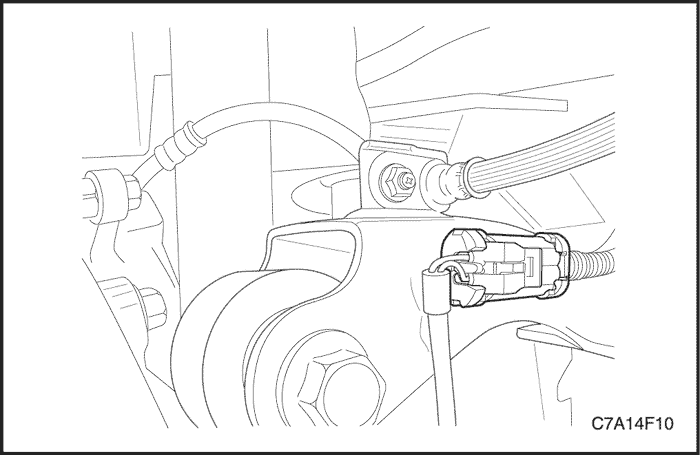
- Disconnect the wheel speed sensor electrical connector.
- Remove the wheel speed sensor bolt.
- Remove the wheel speed sensor.
Installation Procedure
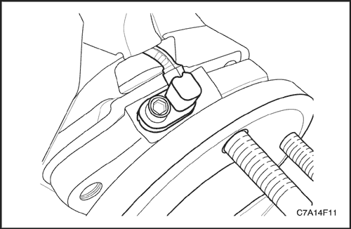
- Install the wheel speed sensor to the wheel bearing/hub assembly.
- Install the wheel speed sensor mounting bolt.
Tighten
Tighten the bolt to 8 N•m (71 lb-in).
- Connect the wheel speed sensor electrical connector.
- Install the tire and wheel assembly.
- Lower the vehicle.
- Install the brake rotor.
Rear Wheel Speed Sensor
Removal Procedure
- Raise and support the vehicle.
- Remove the tire and wheel assembly.
- Remove the brake rotor.
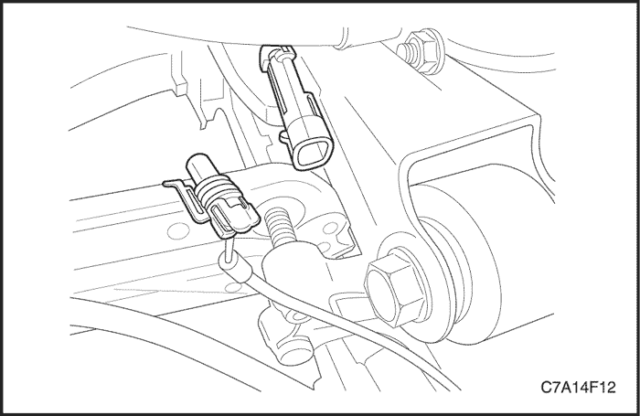
- Disconnect the wheel speed sensor electrical connector.
- Remove the wheel speed sensor bolt.
- Remove the wheel speed sensor through the brake backing plate.
Installation Procedure
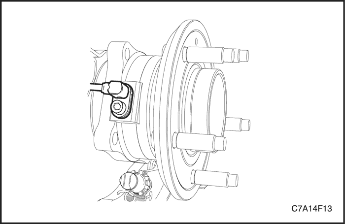
- Install the wheel speed sensor through the drum brake backing plate to the wheel bearing/hub assembly.
- Seat the wheel speed sensor harness grommet into the backing plate.
- Install the wheel speed sensor mounting bolt.
Tighten
Tighten the bolt to 8 N•m (71 lb-in).
- Connect the wheel speed sensor electrical connector.
- Install the brake rotor.
- Install the tire and wheel assembly.
- Lower the vehicle.
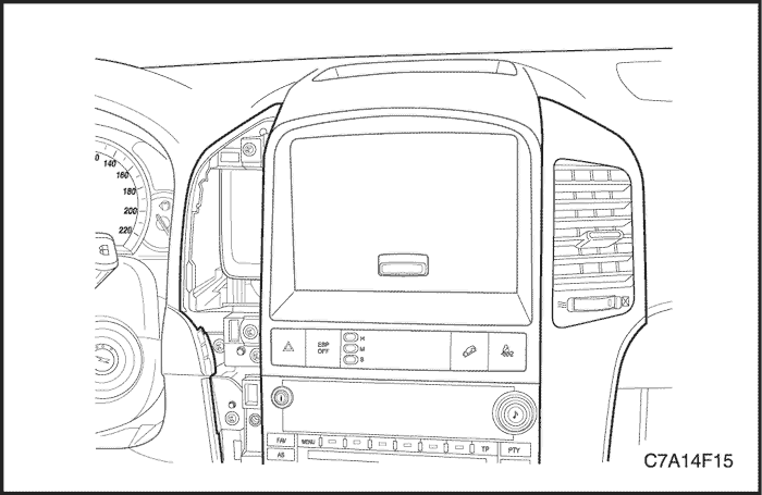
ESP OFF Switch/HDC Switch
Removal Procedure
- Remove the silver moldings from the instrument panel. Refer to Section 9E, Instrumentation/Driver Information.
- Remove the center molding from the instrument panel. Refer to Section 9E, Instrumentation/Driver Information.
- Remove the switch housing from the center molding.

- Disconncect the switch connectors and pull out the switchs from the housing.
Installation Procedure
- Push in the switchs to the housing and connect the switch connectors.
- Install the switch housing to the center molding.
- Install the center molding and silver moldings to the instrument panel. Refer to Section 9E, Instrumentation/Driver Information.
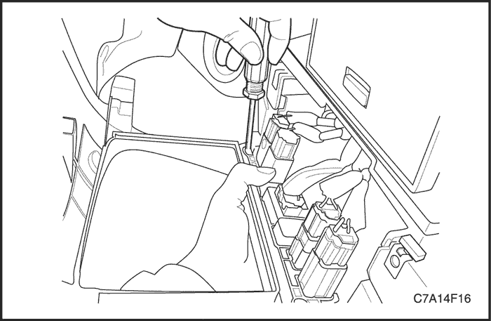
Yaw Rate Sensor
Removal Procedure
- Remove the center console box. Refer to Section 9G, Interior Trim.
- Remove the yaw rate sensor.
Installation Procedure
- Install the yaw rate sensor.
Tighten
Tighten the yaw rate sensor to underbody bolt 10 N•m (7 lb-ft).
- Install the center console box. Refer to Section 9G, Interior Trim.
| © Copyright Chevrolet Europe. All rights reserved |


