SECTION 4G
PARKING BRAKE
SPECIFICATIONS
Fastener Tightening Specifications
Application | N•m | Lb-Ft | Lb-In |
Parking Brake Cable Bracket to Underbody Bolts | 23 | 17 | - |
Parking Brake Lever Assembly-to-Body Panel Bolts | 23 | 17 | - |
MAINTENANCE AND REPAIR
ON-VEHICLE SERVICE


Parking Brake Adjustment - Rear Disc Brakes
Adjustment Procedure
- Release the parking brake.
- Raise and suitably support the vehicle.
- Remove the rear wheels. Refer to Section 2E, Tiresand Wheels.
- Remove the caliper, rotor and hub. Referto Section 4E, Rear Brakes.
- Disconnect the parking brake cable from the back-plate groove.
- Inspect and replace any parts of doubtful strength orquality because of discoloration from heat or stress.
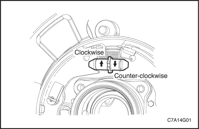
- Adjust the shoe assembly by turning theadjuster nut clockwise to increase the diameter or counter-clockwise to decrease the diameter.
- Install the caliper and the rotor assemblies. Refer to Section 4E, Rear Brakes.
- Install the rear wheels. Refer to Section 2E, Tiresand Wheels.
- Install the parking brake cable to the backplate groove.
- In the vehicle cabin, pull on the parking brake handleand stop after hearing two clicks.
- Turn the rear wheel by hand until the wheel beginsto drag.
- Release the parking brake.
- Turn the rear wheel by hand to check drag and thereadjust the cable, if necessary.
- Repeat the process for the other rear wheel andlower the vehicle.

Parking Brake Warning Lamp Switch
Removal Procedure
- Remove the parking brake/gearshft console hood. Refer to Section 9G, Interior Trim.
- Remove the parking brake warning lamp switch from the parking brake lever assembly and disconnect the connector.
Installation Procedure
- Install the parking brake warning lamp switch and connect the connector.
- Install the parking brake/gearshift console hood. Refer to Section 9G, Interior Trim.

Parking Brake Lever
Removal Procedure
- Release the parking brake.
- Remove the parking brake/gearshift console hood.Refer to Section 9G, Interior Trim.
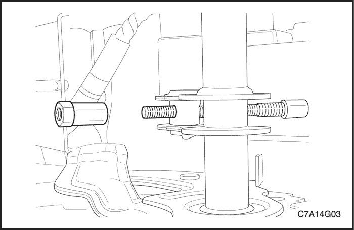
- Measure the thread length from the end of the pull rod to the hex nut.
- Remove the parking brake adjustment nut from the eye bolt pull rod of the parking brake lever assembly.

- Raise and suitable support the vehicle.
- Remove the parking brake cable ends from the parking brake cable equializer.
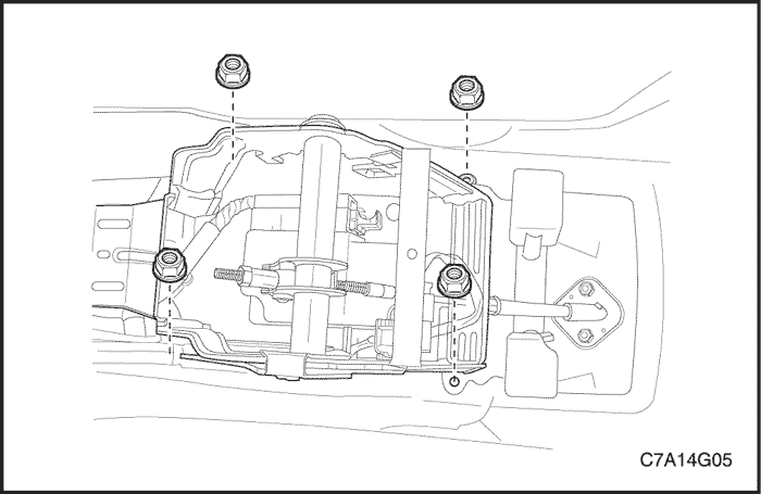
- Remove the bolts which secure the parking brake lever assembly to the body panel.

- Remove the parking brake switch from the parking brake lever assembly.
- Remove the parking brake lever.
Notice : The parking brake warning lamp switch should be replaced ifthe BRAKE warning light in the instrument panel clusterdid not glow when the parking brake was applied withthe ignition ON.
Installation Procedure
- Install the parking brake warning lamp switch to the parking brake lever assembly.
- Install the parking brake lever assembly to the body panel with bolts.
Tighten
Tighten the parking brake lever assembly bolts to 23 N•m (17 lb-ft).
- Install the parking brake cable ends to the parking brake cable equalizer.
- Install the parking brake adjustment nut to the eye bolt pull rod of the parking brake lever assembly and be sure to check the parking brake adjustment by referring the original removal adjustment nut measurement taken in the removal procedure. Refer to "Parking Brake Adjustment - Rear Disc Brakes" in this section.
- Install the parking brake/gearshift console hood. Refer to Section 9G, Interior Trim.
Parking Brake Cable
Removal Procedure
- Release the parking brake.
- Remove the parking brake/gearshift console hood.Refer to Section 9G, Interior Trim.
- Measure the thread length from the end of the pull rod to the hex nut and remove the nut.
- Remove the parking brake cable ends from the parking brake cable equializer and remove the parking brake cable equializer.

- Remove the parking brake cable from the rear backing plate assembly. Refer to Section 4E, Rear Brakes.
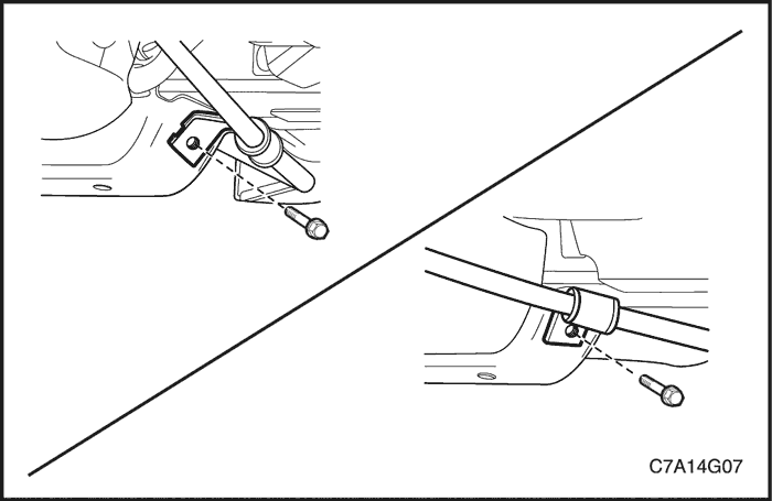
- Remove the parking brake cable to underbody bolts.
- Remove the parking brake cable.
Installation Procedure
- Install the parking brake cable to the rear backing plate asassembly. Refer to Section 4E, Rear Brakes.
- Install the parking brake brake cable bracket to underbody bolts.
Tighten
Tighten the parking brake cable bracket to underbody bolts to 23 N•m (17 lb-ft).
- Install the parking brake cable equializer and the parking brake cable ends to the parking brake cable equializer.
- Install the parking brake adjustment nut to the eye bolt pull rod of the parking brake lever assembly and be sure to check the parking brake adjustment by referring to the original removal adjustment nut measurement taken in the removal procedure. Refer to "Parking Brake Adjustment - Rear Disc Brakes" in this section.
- Install the parking brake/gearshift console hood. Refer to Section 9G, Interior Trim.
GENERAL DESCRIPTIONAND SYSTEM OPERATION
Parking Brake
This braking system uses a BRAKE warning lamp locatedin the instrument panel cluster.
The following conditions will activate the BRAKE lamp:
- The parking brake is applied when the ignition is ON.The lamp will turn off when the parking brake is released.
- The fluid level is below the minimum mark in the mastercylinder reservoir. The lamp will turn off when thefluid level is above the minimum.
- As a test of the lamp circuit, the BRAKE lamp willglow dimly when the ignition is ON, even if the parkingbrake is off and fluid level is above the minimum. Thelamp will turn off when the engine is started.
When the brake is firmly applied, the parking brakeshould hold the vehicle with ample pedal travel remaining.Check for frayed cables, rust, etc. or any conditionthat may inhibit present (or future) free movement of theparking brake lever assembly.


