GENERAL DESCRIPTION AND SYSTEM OPERATION
Transaxle Description
The new automatic transmission (AISIN 55-51LE) is an electronically controlled five-speed automatic transmission.
The transmission is mainly composed of the torque converter, the planetary gear unit, the hydraulic control system and the electric control system.
Electronical Components
Transmission Control Module (TCM)
The TCM primarily controls shift points and lockup engagement. It is located on the driver side under the instrument panel.
The transmission is controlled by an electronic shift system. The Transmission Control Module (TCM) processes input signals. From the information received, the TCM controls the transmission hydraulic system.
The electronic shift system consists of the following :
- Transmission control module (TCM)
- Shift solenoids (SS1, SS2 SS3, SS4, SS5)
- Input shaft speed (ISS) sensor
- Output shaft speed (OSS) sensor
- Transmission Fluid Temperature (TFT) sensor
- Transmission Range (TR) Switch
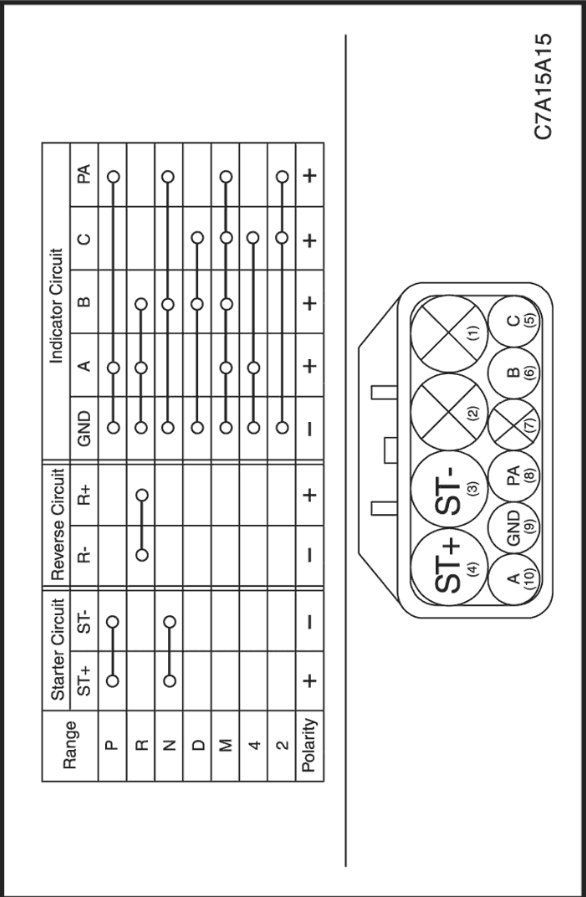
Transmission Range (TR) Switch
Transmission Range (TR) Switch transmits the information which range includes shift lever of A/T to Starter and TCM.
- It is possible for TR switch to start an engine in only "P" and "N". (Prevention of reckless driving)
- TR switch makes backup lamp turn on when reversing.
- It is used for TR switch to shift control.
TR switch transmits the information by combination of starter and reverse circuit to vehicle side directly without TCM.


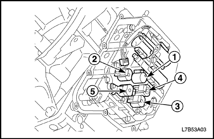
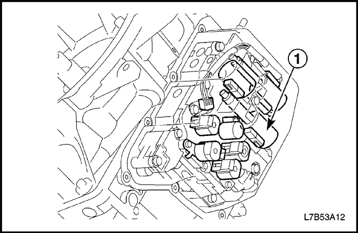
Shift Solenoid No 1, 2, 3, 4, 5 (SS1, SS2, SS3, SS4, SS5)
5 shift solenoids are installed directly in the valve body. The solenoids operate of ON and OFF by the control signal from TCM. Combinations of 5 solenoids, SS1, SS2, SS3, SS4 and SS5 changes gear ranges.
Line Pressure Control Solenoid (SLT)
Line pressure control solenoid (SLT) controls linear throttle pressure by control signal from TCM and line pressure for clutches and brakes to reduce shift shock.

TCC Lock-up Control Solenoid (SLU)
TCC lock up control solenoid (SLU) controls linear SLU pressure by control signal from TCM and hydraulic pressure for lock-up clutch to reduce shift shock.
<Direct control>
1st engine brake - 1st and reverse brake (B3)2nd - 2nd brake (B2)
Shift Pressure Control Solenoid (SLS)
Shift pressure control solenoid (SLS) controls linear SLS pressure by control signal from TCM.
<Direct control>
2nd, 3rd, 4th - 2nd coast brake (B1)5th, Reverse - Direct clutch (C2)
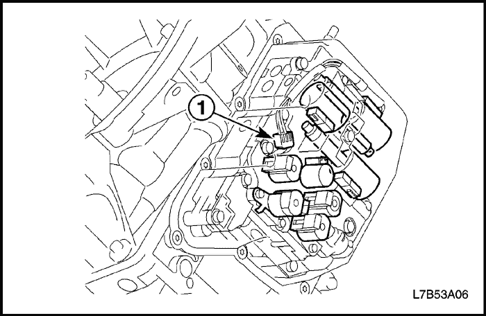
Transmission Fluid Temperature (TFT) Sensor
TFT sensor is located in the valve body.
TFT sensor provides TCM with information on the transmission fluid temperature.
The TCM uses information from the TFT sensor to calculate the gear shift points and to engage the torque converter lockup function.
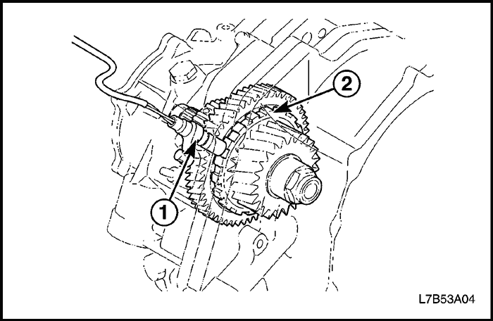
Input Shaft Speed (ISS) Sensor
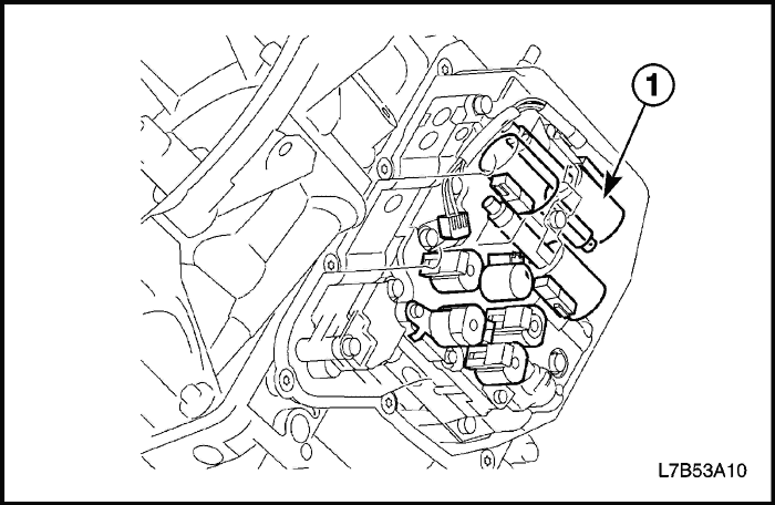
ISS sensor (1) is located on the upper position of the transaxle and detects A/T input speed from the rotation number of the direct clutch drum (2).
They transmit to TCM as a signal.
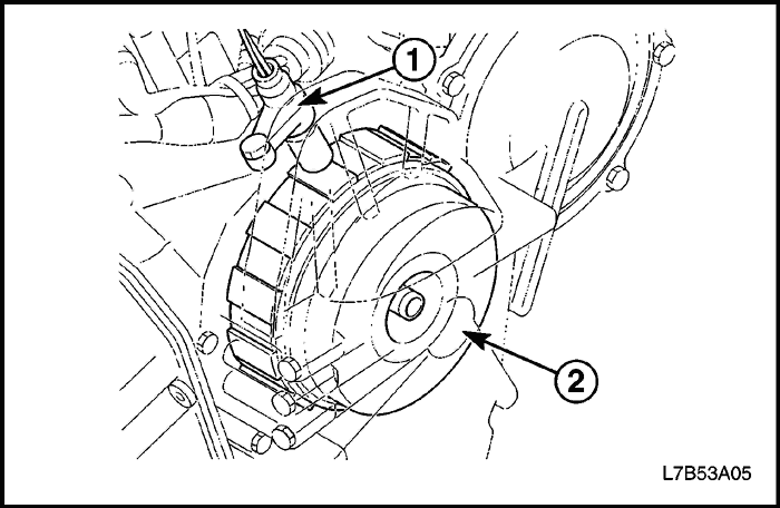
Output Shaft Speed (OSS) Sensor
OSS sensor (1) is located on the upper position of the transaxle and detects the vehicle speed from the rotation number of the parking gear (2).
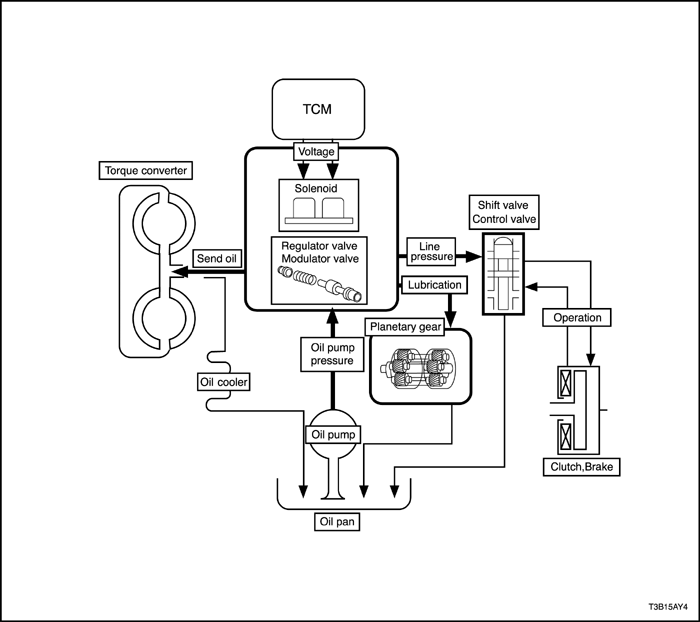
Hydraulic Control System
Based on the hydraulic pressure created by the oil pump, TCM sends signals to solenoid and hydraulic control system governs the hydraulic pressure acting on the torque converter, planetary gear, clutches and brakes in accordance with the vehicle driving conditions.
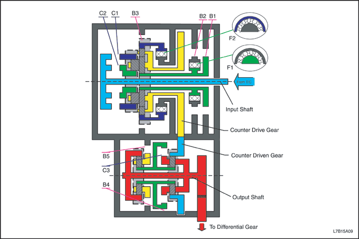
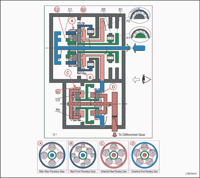
Automatic Transaxle System
Function of Components
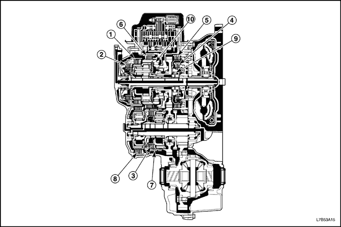
Clutch & Brake | Operation |
C1 | Forward clutch (1) | Connects input shaft and rear ring gear. |
C2 | Direct clutch (2) | Connects input shaft to rear sun gear. |
C3 | Underdrive clutch (3) | Connect underdrive sun gear to underdrive front carrier. |
B1 | 2nd coast brake (4) | Lock front sun gear. |
B2 | 2nd brake (5) | Lock counterclockwise rotation of front sun gear. |
B3 | 1st & reverse brake (6) | Lock front ring gear. |
B4 | Underdrive brake (7) | Lock underdrive sung gear. |
B5 | B5 brake (8) | Lock underdrive rear carrier. |
F1 | 1 way clutch No.1 (9) | Lock counterclockwise rotation of front sun gear, when B2 operations. |
F2 | 1 way clutch No.2 (10) | Lock counterclockwise rotation of front ring gear. |
Operations of Clutches and Brakes
Position | Solenoid | Clutch | Brake | 1Way clutch |
S1 | S2 | S3 | S4 | S5 | C1 | C2 | C3 | B1 | B2 | B3 | B4 | B5 | F1 | F2 |
P | OFF | OFF | OFF | OFF | OFF | OFF | OFF | OFF | OFF | OFF | OFF | OFF | ON | OFF | OFF |
R | V<=7 | OFF | OFF | ON | OFF | ON | OFF | ON | OFF | OFF | OFF | ON | OFF | ON | OFF | OFF |
V>7 | ON | OFF | OFF | OFF | OFF | OFF | OFF | OFF | OFF | OFF | OFF | OFF | ON | OFF | OFF |
N | OFF | OFF | OFF | OFF | OFF | OFF | OFF | OFF | OFF | OFF | OFF | OFF | ON | OFF | OFF |
D, M | D | 1st | ON | ON | ON | OFF | OFF | ON | OFF | OFF | OFF | OFF | OFF | OFF | ON | OFF | ON |
M | 1st | ON | ON | ON | OFF | ON | ON | OFF | OFF | OFF | OFF | ON | OFF | ON | OFF | ON |
2nd | OFF | OFF | ON | OFF | OFF | ON | OFF | OFF | ON | ON | OFF | OFF | ON | ON | OFF |
3rd | OFF | OFF | ON | ON | OFF | ON | OFF | OFF | ON | ON | OFF | ON | OFF | ON | OFF |
4th | OFF | OFF | OFF | ON | OFF | ON | OFF | ON | ON | ON | OFF | OFF | OFF | ON | OFF |
5th | OFF | ON | OFF | ON | OFF | ON | ON | ON | OFF | ON | OFF | OFF | OFF | OFF | OFF |
4 | 1st | ON | ON | ON | OFF | OFF | ON | OFF | OFF | OFF | OFF | OFF | OFF | ON | OFF | ON |
2nd | OFF | OFF | ON | OFF | OFF | ON | OFF | OFF | ON | ON | OFF | OFF | ON | ON | OFF |
3rd | OFF | OFF | ON | ON | OFF | ON | OFF | OFF | ON | ON | OFF | ON | OFF | ON | OFF |
2 | 1st | ON | ON | ON | OFF | ON | ON | OFF | OFF | OFF | OFF | ON | OFF | ON | OFF | ON |
2nd | OFF | OFF | ON | OFF | OFF | ON | OFF | OFF | ON | ON | OFF | OFF | ON | ON | OFF |
D-1st Gear
Position | Solenoid | Clutch | Brake | 1 way Clutch |
S1 | S2 | S3 | S4 | S5 | C1 | C2 | C3 | B1 | B2 | B3 | B4 | B5 | F1 | F2 |
D | 1st | ON | ON | ON | OFF | OFF | ON | OFF | OFF | OFF | OFF | OFF | OFF | ON | OFF | ON |
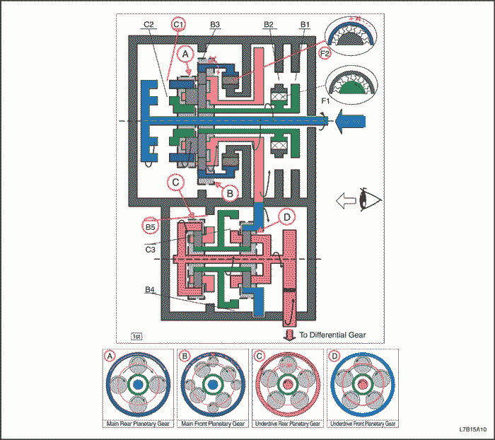
"D" - 1st Gear
- Input shaft rotates clockwise.
- C1 operates (Connect input shaft to rear planetary ring gear)
- Rear planetary ring gear rotates clockwise.
- Rear planetary pinion rotates itself clockwise.
- Front large planetary pinion rotates itself clockwise for rear planetary pinion and one.
- Front small planetary pinion rotates itself counterclockwise.
- Front ring gear is going to rotate counterclockwise.
- F2 operates (Lock counterclockwise rotation of Front ring gear).
- Front & rear planetary carrier revolves clockwise due to reaction force of front small pinion.
- Counter drive gear rotates clockwise for front & rear planetary carrier and one.
- Counter driven gear rotates counterclockwise.
- Front planetary ring gear rotates counterclockwise for counter driven gear and one.
- Front planetary pinion rotates itself counterclockwise.
- Front planetary sun gear rotates clockwise.
- Rear planetary sun gear rotates clockwise for front planetary sun gear and one.
- Rear planetary pinion rotates itself counterclockwise.
- B5 operates (Lock rotation of rear carrier).
- Rear planetary ring gear rotates counterclockwise.
- Front carrier and differential drive pinion gear rotates counterclockwise for rear ring gear and one.
- Differential rotates clockwise.
( Engine Brake)
- Counter drive gear and main front & rear planetary carrier rotates clockwise.
- Rear planetary carrier rotates clockwise, but rear planetary pinion revolves clockwise while rotating itself counterclockwise due to resistance of rear planetary ring gear.
- Front large pinion revolves clockwise while rotating itself counterclockwise and front small pinion revolves clockwise while rotating itself clockwise. And front carrier revolves clockwise.
- Front ring gear rotates clockwise due to rotation itself clockwise of front small pinion, but driving force loses due to free of F2. Therefore engine brake does not operate.
D-2nd Gear
Position | Solenoid | Clutch | Brake | 1 way Clutch |
S1 | S2 | S3 | S4 | S5 | C1 | C2 | C3 | B1 | B2 | B3 | B4 | B5 | F1 | F2 |
D | 2nd | OFF | OFF | ON | OFF | OFF | ON | OFF | OFF | ON | ON | OFF | OFF | ON | ON | OFF |
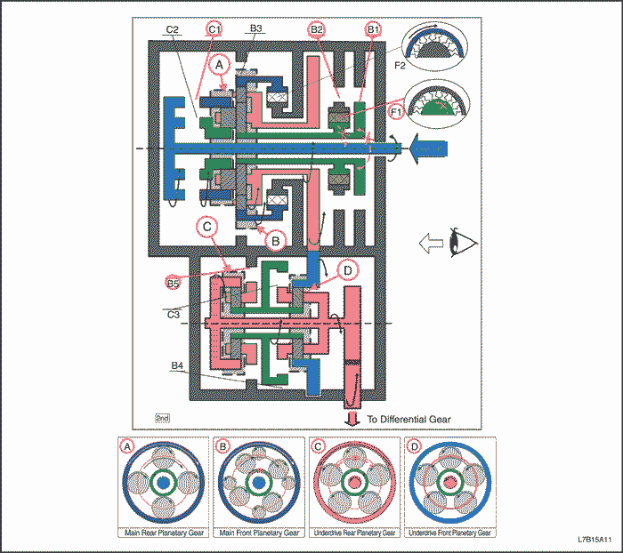
"D" - 2nd Gear
- Input shaft rotates clockwise.
- C1 operates (Connect input shaft to rear planetary ring gear)
- Rear planetary ring gear rotates clockwise.
- Rear planetary pinion rotates itself clockwise.
- Front large planetary pinion rotates itself clockwise for rear planetary pinion and one.
- B2 & F1 and B1 operates (Lock rotation of front planetary sun gear)
- Front & rear planetary carrier revolves clockwise due to reaction force of front large pinion.
- Counter drive gear rotates clockwise for front & rear planetary carrier and one.
- Counter driven gear rotates counterclockwise.
- Front planetary ring gear rotates counterclockwise for counter driven gear and one.
- Front planetary pinion rotates itself counterclockwise.
- Front planetary sun gear rotates clockwise.
- Rear planetary sun gear rotates clockwise for front planetary sun gear and one.
- Rear planetary pinion rotates itself counterclockwise.
- B5 operates (Lock rotation of rear carrier)
- Rear planetary ring gear rotates counterclockwise.
- Front carrier and differential drive pinion gear rotates counterclockwise for rear ring gear and one.
- Differential rotates clockwise.
( Engine Brake)
- Driving force is connected to input shaft directly without 1 way clutch. Therefore engine brake operates.
D-3rd Gear
Position | Solenoid | Clutch | Brake | 1 way Clutch |
S1 | S2 | S3 | S4 | S5 | C1 | C2 | C3 | B1 | B2 | B3 | B4 | B5 | F1 | F2 |
D | 3rd | OFF | OFF | ON | ON | OFF | ON | OFF | OFF | ON | ON | OFF | ON | OFF | ON | OFF |
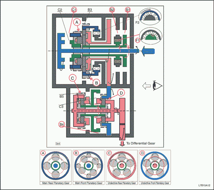
"D" - 3rd Gear
- Input shaft rotates clockwise.
- C1 operates (Connect input shaft to rear planetary ring gear)
- Rear planetary ring gear rotates clockwise.
- Rear planetary pinion rotates itself clockwise.
- Front large planetary pinion rotates itself clockwise for rear planetary pinion and one.
- B2 & F1 and B1 operates (Lock rotation of front planetary sun gear)
- Front & rear planetary carrier revolves clockwise due to reaction force of front large pinion.
- Counter drive gear rotates clockwise for front & rear planetary carrier and one.
- Counter driven gear rotates counterclockwise.
- Front planetary ring gear rotates counterclockwise for counter driven gear and one.
- Front planetary pinion rotates itself counterclockwise.
- B4 operates (Lock rotation of front & rear planetary sun gear)
- Front planetary carrier revolves counterclockwise due to reaction force of front planetary pinion.
- Rear ring gear and differential drive pinion gear rotates counterclockwise for front carrier and one.
- Differential rotates clockwise.
( Engine Brake)
- Driving force is connected to input shaft directly without 1 way clutch. Therefore engine brake operates.
D-4th Gear
Position | Solenoid | Clutch | Brake | 1 way Clutch |
S1 | S2 | S3 | S4 | S5 | C1 | C2 | C3 | B1 | B2 | B3 | B4 | B5 | F1 | F2 |
D | 4th | OFF | OFF | OFF | ON | OFF | ON | OFF | ON | ON | ON | OFF | OFF | OFF | ON | OFF |
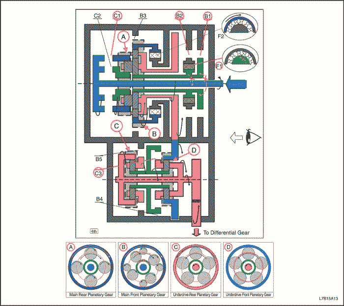
"D" - 4th Gear
- Input shaft rotates clockwise.
- C1 operates (Connect input shaft to rear planetary ring gear)
- Rear planetary ring gear rotates clockwise.
- Rear planetary pinion rotates itself clockwise.
- Front large planetary pinion rotates itself clockwise for rear planetary pinion and one.
- B2 & F1 and B1 operates (Lock rotation of front planetary sun gear)
- Front & rear planetary carrier revolves clockwise due to reaction force of front large pinion.
- Counter drive gear rotates clockwise for front & rear planetary carrier and one.
- Counter driven gear rotates counterclockwise.
- Front planetary ring gear rotates counterclockwise for counter driven gear and one.
- C3 operates (Connect planetary sun gear to front planetary carrier )
- Front planetary pinion can not rotate itself, and underdrive unit rotates counterclockwise as one.
- Differential drive pinion gear rotates counterclockwise for underdrive unit and one.
- Differential rotates clockwise.
<Engine Brake>
- Driving force is connected to input shaft directly without 1 way clutch. Therefore engine brake operates.
D-5th Gear
Position | Solenoid | Clutch | Brake | 1 way Clutch |
S1 | S2 | S3 | S4 | S5 | C1 | C2 | C3 | B1 | B2 | B3 | B4 | B5 | F1 | F2 |
D | 5th | OFF | ON | OFF | ON | OFF | ON | ON | ON | OFF | ON | OFF | OFF | OFF | OFF | OFF |
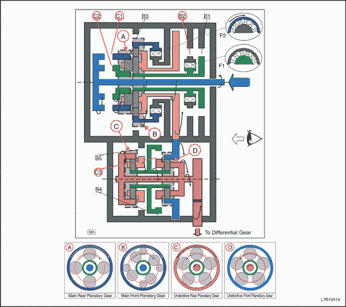
"D" - 5th Gear
- Input shaft rotates clockwise.
- C1 operates (Connect input shaft to rear planetary ring gear)
- C2 operates (Connect input shaft to rear planetary sun gear)
- Rear planetary pinion can not rotate itself, and rear planetary unit rotates clockwise as one.
- Front large planetary pinion can not rotate itself for rear planetary pinion and one, and front planetary unit rotates clockwise as one.
- Counter drive gear rotates clockwise for front planetary unit and one.
- Counter driven gear rotates counterclockwise.
- Front planetary ring gear rotates counterclockwise for counter driven gear and one.
- C3 operates (Connect planetary sun gear to front planetary carrier )
- Front planetary pinion can not rotate itself, and underdrive unit rotates counterclockwise as one.
- Differential drive pinion gear rotates counterclockwise for underdrive unit and one.
- Differential rotates clockwise.
<Engine Brake>
- Driving force is connected to input shaft directly without 1 way clutch. Therefore engine brake operates.
Reverse Gear
Position | Solenoid | Clutch | Brake | 1 way Clutch |
S1 | S2 | S3 | S4 | S5 | C1 | C2 | C3 | B1 | B2 | B3 | B4 | B5 | F1 | F2 |
R | V<=7km/h | OFF | OFF | ON | OFF | ON | OFF | ON | OFF | OFF | OFF | ON | OFF | ON | OFF | OFF |
V>7km/h | ON | OFF | OFF | OFF | OFF | OFF | OFF | OFF | OFF | OFF | OFF | OFF | ON | OFF | OFF |
Reverse Gear
- Input shaft rotates clockwise.
- C2 operates (Connect input shaft to rear planetary sun gear)
- Rear planetary sun gear rotates clockwise.
- Rear planetary pinion rotates itself counterclockwise.
- Front large planetary pinion rotates itself counterclockwise for rear planetary pinion and one.
- Front small planetary pinion rotates itself clockwise.
- B3 operates (Lock rotation of front planetary ring gear)
- Front & rear carrier revolves counterclockwise due to reaction force of front small pinion.
- Counter drive gear rotates counterclockwise for front & rear planetary carrier and one.
- Counter driven gear rotates clockwise.
- Front planetary ring gear rotates clockwise for counter driven gear and one.
- Front planetary pinion rotates itself clockwise.
- Front planetary sun gear rotates counterclockwise.
- Rear planetary sun gear rotates counterclockwise for front planetary sun gear and one.
- Rear planetary pinion rotates itself clockwise.
- B5 operates (Lock rotation of rear carrier)
- Rear planetary ring gear rotates clockwise.
- Front carrier and differential drive pinion gear rotates clockwise for rear ring gear and one.
- Differential rotates counterclockwise.
<Engine Brake>
- Driving force is connected to input shaft directly without 1 way clutch. Therefore engine brake operates.
Control Functions of TCM
Shift Control and Lock-up Control
According to each shift schedule, TCM sends signals to the S1, S2, S3, S4, S5 which operates ON/OFF control "Shift Control" and the TCC lock up control solenoid (SLU) which operates linear control "Lock-up Control" on the basis of the vehicle speed and the throttle opening.
<Each solenoid operation>
Gear | S1 | S2 | S3 | S4 | S5 |
1st | ON | ON | ON | OFF | OFF |
2nd | OFF | OFF | ON | OFF | OFF |
3rd | OFF | OFF | ON | ON | OFF |
4th | OFF | OFF | OFF | ON | OFF |
5th | OFF | ON | OFF | ON | OFF |
55-51LE for automatic transaxle does not have several driving mode that user can select. Basically TCM programmed for "Economy mode", but TCM changes to several shift schedule automatically according to specified condition. But, only "Winter mode" can be chosen by the switch.
- Driver's adaptive shift control (Economy, Medium, Sport mode)
- Economy mode is used for normal driving condition after ignition ON. And driver's liking is detected by using fuzzy logic from accelerator operation. This control changes shift points to Economy (low speed), Medium(middle speed) and Sport(high speed) according to the liking degree.
Start (1) & (2) | (1) "D" | (2) Vehicle speed >= 5 km/h (3 mph) |
End (1) or (2) or (3) | (1) Except "D" | (2) Vehicle speed > 240 km/h (149 mph) |
(3) Driver's liking detection is Economy mode |
- Winter mode
- This mode is used for vehicle start on a slippery road due to pushing the winter mode switch. (Vehicle start in 3rd gear)
Range | Winter |
D | 3(L) ↔ 4(L) ↔ 5(L) |
↔: Shift up/down, (L) : Lock-up Operation
- Upslope mode
- When TCM detects upslope from load of engine torque and decrease of acceleration, this mode changes shift points in high-speed side according to the upslope degree and avoids busy shift of A/T.
- Downslope mode
- When TCM detects downslope from increase of acceleration with accelerator full close, this mode operates moderate engine brake by changing shift points in high-speed side.
- Hot mode control
- This control lowers ATF temperature by changing shift points when the temperature is extremely high. (ATF temperature > 140°C (284°F))
- Altitude control
- This control makes up for low engine power by establishing shift points at a slightly higher vehicle speed range in high altitude where air pressure is low.
- Cold offset control
- This control makes up for low engine torque by establishing shift points at a slightly higher vehicle speed range when air temperature is extremely low. (Engine coolant temperature < -30°C (-22°F))
Manual Shift Control (Tap Mode)
Driver oneself can select favorite gear and enjoy sports driving of manual transmission sense by shifting shift lever from "D" to manual gear position and Manual+(Up shift) / Manual-(Down shift). But lock-up control is operated automatically. Shift control is operated again by shifting from manual gear position to "D".
Lock-up Cut Control
This control cuts lock-up operation at shift down or idle condition and avoid engine stall by depressing brake pedal at low speed driving.
Up/Down Learning Control
This control learns the pressure to each clutch or brake in order to reduce shifting shock at each shifting (Up, Down, Manual down, Coast down).
<Learning control method>
(1) 65°C (149°F) =< Oil temperature < 110°C (230°F)
(2) Constant low throttle opening (about 20-30%)
(3) Plenty shifting interval (about 3 sec)
(4) Repeat each shifting about 10 times
N-D Shift Control
This control improves the N-D shift quality due to controlling line pressure control solenoid according to forward clutch (C1) piston stroke learned in N-D learning control and applying best hydraulic pressure to forward clutch (C1) at N-D shift.
N-D Learning Control
This control learns the forward clutch (1) hydraulic pressure due to monitoring a forward clutch (1) engaging time and a rotation change rate.
Start (1) & (2) & (3) & (4) | (1) 500 rpm =< Engine speed < 1,200 rpm |
(2) 65°C (149°F) =< Oil temperature < 110°C (230°F) |
(3) 450 rpm =< forward clutch (C1) revolution < 1,200 rpm |
(4) Throttle opening < 3.0 % |
<Learning control method>
(1) When above start condition
(2) Shifting interval more than 3 sec
(3) Repeat N-D shifting about 10 times
N-R Shift Control
This control improves the N-R shift quality due to controlling shift pressure control solenoid according to direct clutch (C2) piston stroke learned in N-R learning control and applying best hydraulic pressure to C2 clutch at N-R shift.
N-R Learning Control
This control learns the direct clutch (C2) hydraulic pressure due to monitoring a C2 clutch engaging time and a rotation change rate.
Start (1) & (2) & (3) & (4) | (1) 500 rpm =< Engine speed < 1,200 rpm |
(2) 65°C (149°F) =< Oil temperature < 110°C (230°F) |
(3) 450 rpm =< forward clutch (C1) revolution < 1,200 rpm |
(4) Throttle opening < 3.0 % |
<Learning control method>
(1) When above start condition
(2) Shifting interval more than 3 sec
(3) Repeat N-R shifting about 10 times
Torque Reduction Control
This control improves the shift quality due to sending torque reduction request signal from TCM to ECM and cutting engine torque increase of shift at N-D shift, N-R shift and 1↔2↔3↔4↔5.
If accelerator pedal is depressed rapidly, this control establishes the upper limit value of engine torque and avoids "Engine flare" at 2↔3, 3↔4 and 4=>2 of "clutch to clutch shift".
Transmission Adaptive Learn Procedure
Perform the transmission adaptive learn procedure after any of the following service procedures :
- Transmission Control Module (TCM) replacement
- TCM calibration change
- Control valve body replacement
- Transaxle overhaul
- Transaxle replacement
- Drive the vehicle to warm the transaxle fluid until 65-110°C (150-230°F). The adaptive learn procedure will not work unless transaxle fluid is the correct temperature.
- Reset the transaxle adaptive learns using a scan tool.
- Perform the following steps for the garage shifts adaptive learn.
- Apply the parking brake and the foot brake.
- Shift from NEUTRAL to REVERSE and keep in REVERSE for 3 seconds.
- Shift from REVERSE to NEUTRAL.
- Repeat the above two steps five times.
- Shift from NEUTRAL to DRIVE and keep in DRIVE for 3 seconds.
- Shift from DRIVE to NEUTRAL.
- Repeat the above two steps five times.
- Perform the following steps for the Up/Down shifting adaptive learn.
- Drive the vehicle in DRIVE with light (15-20 percent) throttle until above 50 km/h (31 mph) in 4th gear.
- Decelerate and apply the brakes until vehicle comes to a stop. Brake the vehicle so that it takes at least 14 seconds.
- Repeat the above steps five times.
- In case the shift indicator positions are labeled P, R, N, D, 4, 2
Perform the following steps for 4→2 Manual down shift adaptive learn (No Tap shift).- Drive the vehicle in "4" until over 25 km/h (16 mph) in 2nd with any throttle position.
- Decelerate, shift from "4" to "2" manually and stop the vehicle.
- Repeat the above two steps ten times.
- In case the shift indicator positions are labeled P, R, N, D, M
Perform the following steps for 2→1 Tap down shift adaptive learn (Tap shift).- Drive the vehicle in "Tap 2" until over 25 km/h (16 mph) in 2nd with any throttle position.
- Decelerate, shift from "Tap 2" to "Tap 1" manually and stop the vehicle.
- Repeat the above two steps ten times.
Important : If shift quality does not improve, ensure the TCM has the correct transmission calibration.
- Confirm shift quality.
| © Copyright Chevrolet Europe. All rights reserved |


