MAINTENANCE AND REPAIR
ON-VEHICLE SERVICE
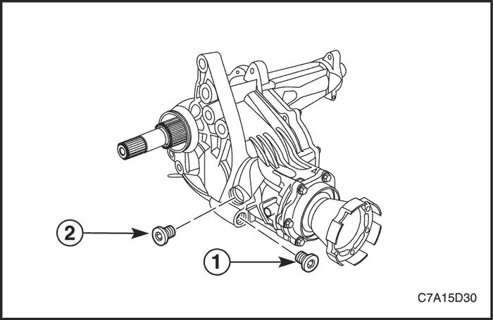


Transfer Case Fluid Replacement
Removal Procedure
- Raise and support the vehicle.
- Remove the drain plug (1).


- Remove the fill plug (2).


Installation Procedure
- Install the drain plug (1).
Tighten
Tighten the drain plug (1) to 39 N•m (29 lb-ft).


- Fill the transfer case with synthetic hypoid 75W-90 to the bottom of the fill plug hole, when the vehicle is on a level surface.
- Install the fill plug (2).
Tighten
Tighten the fill plug (2) to 39 N•m (29 lb-ft).
- Lower the vehicle.
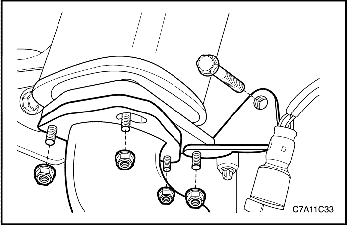


Transfer Case
Removal Procedure
- Raise and support the vehicle.
- Remove the exhaust front pipe. Refer to Section 1G1, Engine Exhaust - 2.0 DIESEL ; Section 1G2, Engine Exhaust - FAM II 2.4D ; Section 1G3, Engine Exhaust - HFV6 3.2L.
- Remove the propeller shaft. Refer to Section 3B, Rear Drive Axle.
- Remove the right drive axle. Refer to Section 3A, Front Drive Axle.
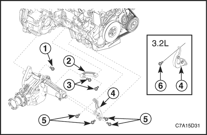


- Remove the upper transfer case bolt (1).
- Remove the transfer case brace bolts (3) and the brace (2).
- Remove the transfer case bracket bolts (5, 6) and the bracket (4).
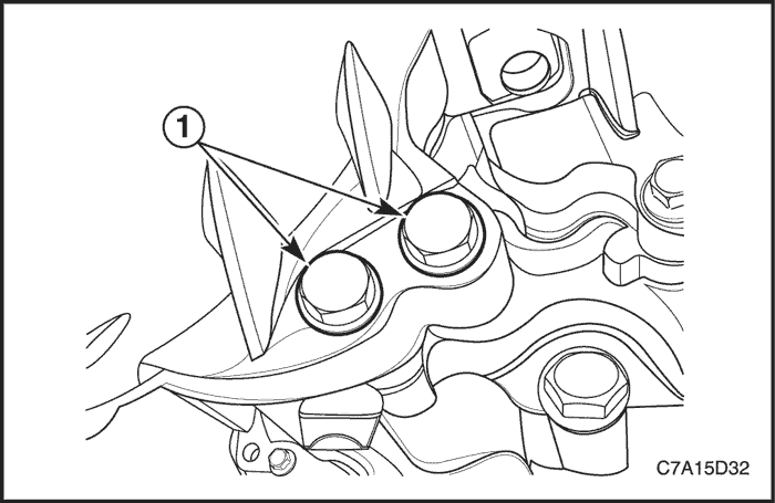


- Remove the lower transfer case bolts (1).
- Support the transfer case using the supporting jack.
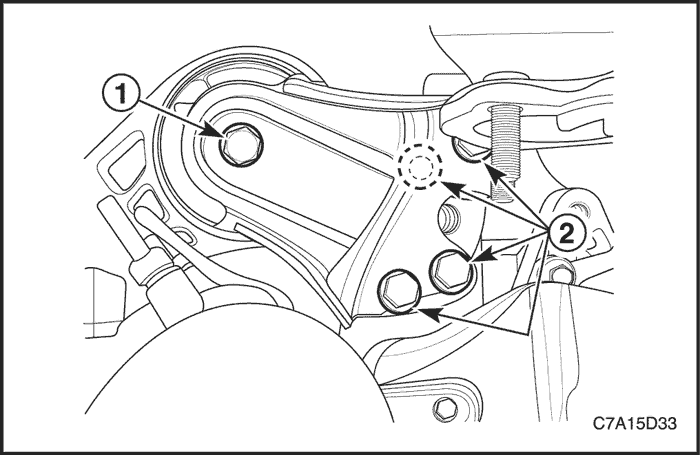


- Remove the transaxle rear mount-to-bracket through bolt (1).
- Remove the rear transaxle bracket mounting bolts and nut (2).
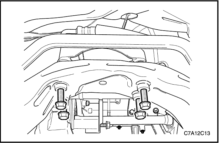


- Remove the transaxle rear mount retaining bolts from the cradle.
- Remove the rear transaxle bracket.
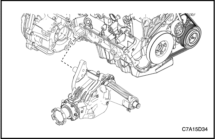


- Remove the transfer case from the transaxle.
- Plug the transaxle to minimize the transaxle fluid loss.


Installation Procedure
- Install the transfer case into the transaxle.


- Install the rear transaxle bracket.
- Install the transaxle rear mount retaining bolts to the cradle.
Tighten
Tighten the transaxle rear mount retaining bolts to 90 N•m (66 lb-ft).


- Install the transaxle rear mount-to-bracket through bolt (1).
Tighten
Tighten the transaxle rear mount-to-bracket through bolt (1) to 90 N•m (66 lb-ft).
- Install the rear transaxle bracket mounting bolts and nut (2).
Tighten
Tighten the rear transaxle bracket mounting bolts and nut (2) to 90 N•m (66 lb-ft).


- Install the lower transfer case bolts (1).
Tighten
Tighten the lower transfer case bolts (1) to 75 N•m (55 lb-ft).


- Install the upper transfer case bolt (1).
Tighten
Tighten the upper transfer case bolt (1) to 75 N•m (55 lb-ft).
- Install the transfer case brace (2) and bolts (3).
Tighten
Tighten the transfer case brace bolts (3) to 60 N•m (44 lb-ft).
- Install the transfer case bracket (4) and bolts (5).
Tighten
Tighten the transfer case bracket bolts (5) to 60 N•m (44 lb-ft).
- If the vehicle is equipped with 3.2L engine, Install the transfer case bracket bolt (6) and other four bolts (5).
Tighten
Tighten the transfer case bracket bolt (6) to 40 N•m (30 lb-ft).
Tighten the other four transfer case bracket bolts (5) to 60 N•m (44 lb-ft).


- Install the right drive axle. Refer to Section 3A, Front Drive Axle.
- Install the propeller shaft. Refer to Section 3B, Rear Drive Axle.
- Install the exhaust front pipe. Refer to Section 1G1, Engine Exhaust - 2.0 DIESEL ; Section 1G2, Engine Exhaust - FAM II 2.4D ; Section 1G3, Engine Exhaust - HFV6 3.2L.
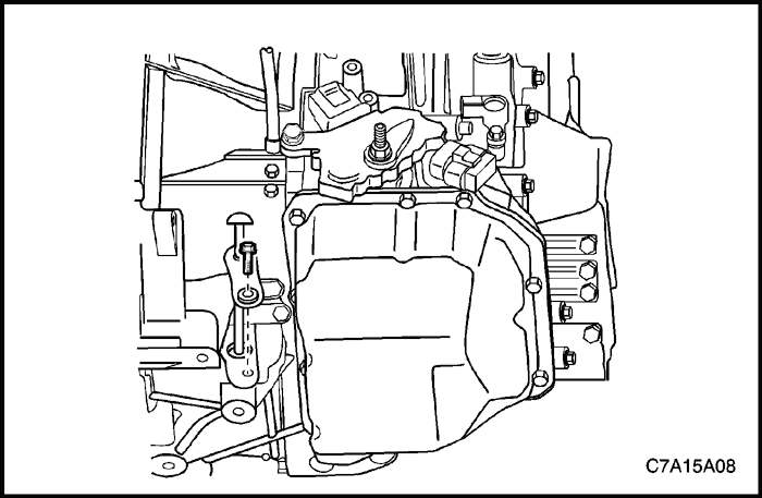


- Lower the vehicle.
- Check the transaxle oil level and fill as required. Refer to Section 5A, AISIN 55–51LE Automatic Transaxle.
UNIT REPAIR


Transfer Case Disassembly
Tools Required
Disassembly Procedure
- Remove the transfer case from the vehicle. Refer to "Transfer Case" in this section.
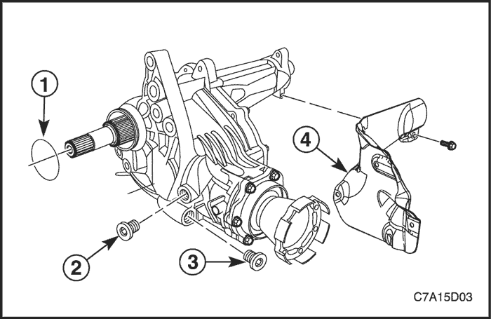


- Remove the transfer case O-ring seal (1).
- Remove the transfer case fill plug (2) and transfer case drain plug (3).
- Remove the transfer case heat shield bolts and heat shield (4).
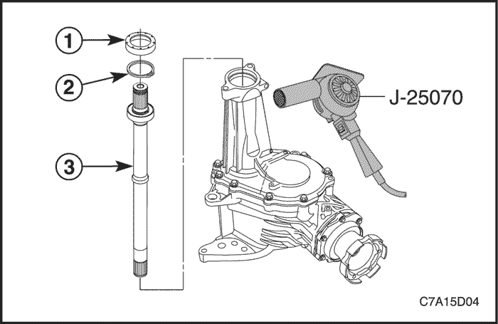


- Remove the front wheel drive shaft shield (1) using the suitable puller.
- Remove the front wheel drive retainer (2).
- Heat the end of transfer case housing with heat gun J-25070for the easy removal of the front wheel drive intermediate shaft.
- Remove the front wheel drive intermediate shaft (3) from the transfer case.
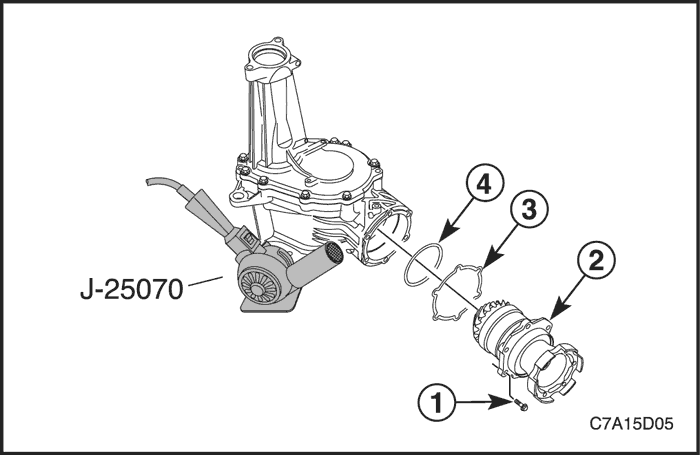


- Heat the flange area of the drive housing with heat gun J-25070 for the easy removal of the transfer case rear output drive housing.
Important : Locate 2 screwdrivers or prybars to the flange area of the drive housing to ease removal.
- Remove the case rear output drive shaft housing bolts (1) and the housing (2) from the transfer case.
- Remove the transfer case rear output shim (3).
- Remove the transfer case rear output drive shaft housing seal O-ring (4) and discard it.
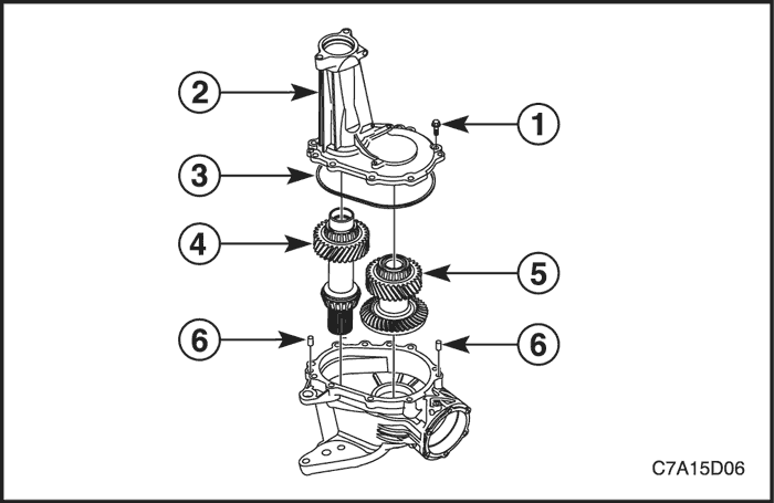


- Remove the 11 transfer case half bolts (1) and the right side transfer case (2).
- Remove the transfer case seal(3) from the transfer case (2).
- Remove the transfer case input shaft (4) and transfer case rear output drive shaft (5) from the left side transfer case.
Important : Remove the transfer case half locating pins (6) only if damaged. Inspect the case for similar damage.


Rear Output Drive Housing Disassembly
Tools Required
DT-48146 Press Support
J-08614-A Pinion Flange Holder and Remover
J-29873 Injector Nozzle Socket (30mm)
Disassembly Procedure
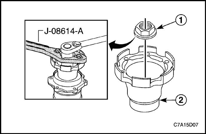
- Install pinion flange holder and remover J-08614-A to the rear output shaft flange (2).
- Using a ratchet with the 30mm socket or J-29873, remove the transfer case rear output drive gear nut (1).
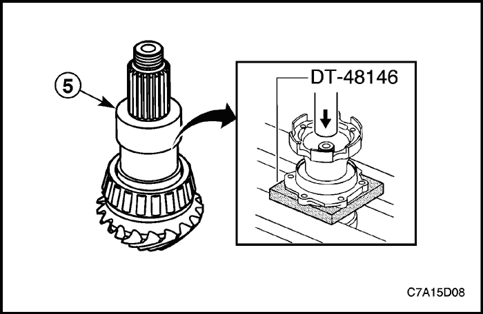


- Using a press and press support DT-48146, remove the output shaft (5) from the housing.
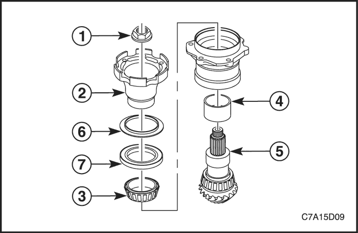


- Remove the transfer case rear output shaft bearing assembly (3) and the transfer case rear output shaft bearing spacer (4).
- Remove the transfer case rear output shaft seal (7) and discard it.
- Remove the transfer case rear output shaft oil slinger (6) only if damaged. Use a punch and hammer to remove it.


Intermediate Drive Shaft Disassembly
Tools Required
J-22912-01 Universal Bearing Puller
Disassembly Procedure
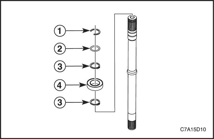
- Remove the half shaft retainer (1), O-ring (2) and front wheel drive intermediate shaft bearing retainers (3) from the shaft.
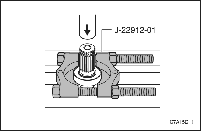


- Using a press with universal bearing puller J-22912-01, remove the front wheel drive intermediate shaft bearing assembly (4).


Transfer Case Cleaning And Inspection
Inspection Procedure
Important :
- Inspect all components or sub-components and perform any repair procedure necessary to fix the damage. If the damage cannot be repaired, replace the component or sub-component as indicated.
- Clean the left and right transfer case in cleaning solvent and air dry.
Important : Inspect for cracks, broken areas, or other damage. The transfer case assembly must be replaced if damage is found.
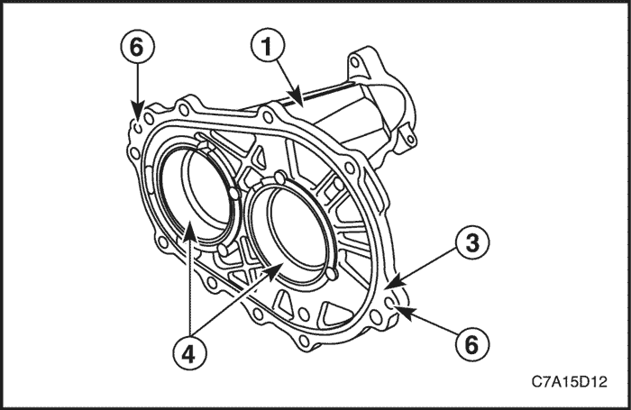
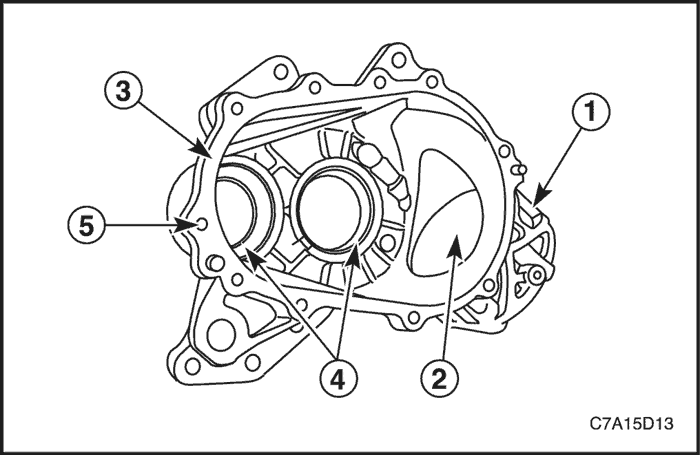
- Inspect the left and right transfer case (1).


Important : Repair small scratches or nicks with light sanding.
- Inspect the transfer case rear output drive housing bore (2).
Important : Repair small scratches or nicks with a soft stone.
- Inspect the case sealing surface (3).
Important : Replace the transfer case assembly if a bearing has spun or if cracks are detected.
- Inspect the transfer case bearing races (4).
Important : Repair any damaged threads.
- Inspect the transfer case thread bolt holes (5).
- Inspect the transfer case half locating pin holes (6).


Rear Output Drive Housing Cleaning And Inspection
Inspection Procedure
Important :
- Inspect all components or sub-components and perform any repair procedure necessary to fix the damage. If the damage cannot be repaired, replace the component or sub-component as indicated.
- Clean all components in cleaning solvent and air dry.
Important : Replace if flange, threaded holes, or splines are damaged.
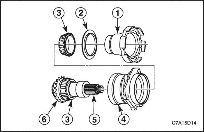
- Inspect the transfer case rear output shaft flange (1) for corrosion, excessive wear, or damage.
Important : Replace the slinger if damaged, cracked, loose, or distorted.
- Inspect the transfer case rear output shaft oil slinger (2).
- Replace the transfer case rear output shaft bearing assembly (3) for roughness, spalling, or pitting.
Important :
- Inspect for cracks, broken areas, or other damage.
- Inspect bearing races for roughness, brinelling, or pitting.
- Inspect the O-ring channel for porosity or damage.
Important : Scratches or nicks in other areas may be repaired with light sanding.
- Inspect the transfer case rear output drive housing (4).
- Inspect the transfer case rear output shaft splines (5) for damage and press fit to flange.
- Inspect the transfer case rear output shaft (6) for pitting, excessive wear, or damage.
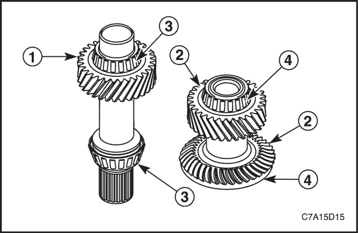


Input Shaft And Output Shaft Cleaning And Inspection
Inspection Procedure
Important :
- Inspect all components or sub-components and perform any repair procedure necessary to fix the damage. If the damage cannot be repaired, replace the component or sub-component as indicated.
- Clean all components in cleaning solvent and air dry.
- Inspect the transfer case input shaft gears (1) for pitting, excessive wear, or damage.
- Inspect the transfer case rear output drive shaft gears (2) for pitting, excessive wear, or damage.
- Inspect the transfer case input shaft bearing assemblies (3) for roughness, spalling, pitting.
- Inspect the transfer case rear output drive shaft bearing assemblies (4) for roughness, spalling, pitting.
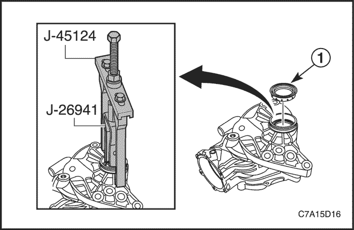


Right Input Shaft Seal Replacement
Tools Required
DT-48074 Input and Output Shaft Seal Installer
J-8092 Driver Handle
J-26941 Bushing and Bearing Remover
J-45124 Removal Bridge
Removal Procedure
Important : Do not use a screwdriver or punch to remove the seal. Using a screwdriver or punch to remove the seal may damage the aluminum housing sealing surface.
- Using removal bridge J-45124 and bushing and bearing remover J-26941, remove the transfer case right input shaft seal.
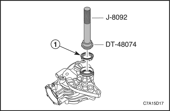


Installation Procedure
- Using input and output shaft seal installer DT-48074 and driver handle J-8092, install the transfer case right input shaft seal (1).
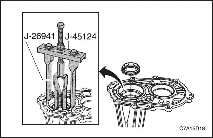


Left Input Shaft Seal Replacement
Tools Required
DT-48074 Input and Output Shaft Seal Installer
J-8092 Driver Handle
J-26941 Bushing and Bearing Remover
J-45124 Removal Bridge
Removal Procedure
Important : Do not use a screwdriver or punch to remove the seal. Using a screwdriver or punch to remove the seal may damage the aluminum housing sealing surface.
- Using removal bridge J-45124 and bushing and bearing remover J-26941, remove the transfer case left input shaft seal.


Installation Procedure
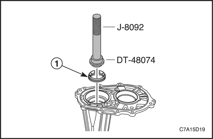
- Using input and output shaft seal installer DT-48074 and driver handle J-8092, install the transfer case left input shaft seal (1)


Front Drive Axle Intermediate Shaft Seal Replacement
Tools Required
DT-48078 Inner Drive Shaft Seal Installer
J-8092 Driver Handle
Removal Procedure
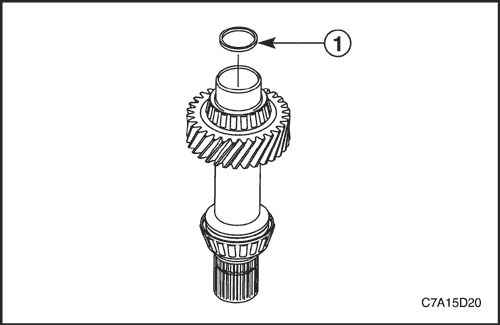
- Remove the front drive axle intermediate shaft seal assembly (1).


Installation Procedure
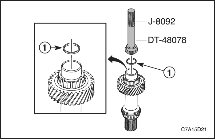
Important : DT-48078 seats the seal to a specific depth. Other installation methods may set the seal to a non-functional depth.
- Using inner drive shaft seal installer DT-48078 and driver handle J-8092, install the front drive axle intermediate shaft seal assembly (1).


Intermediate Drive Shaft Assembly
Tools Required
J-22912-01 Universal Bearing Puller
Assembly Procedure
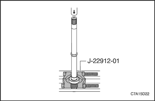
- Using a press with Universal Bearing Puller J-22912-01, install the front wheel drive intermediate shaft bearing assembly.
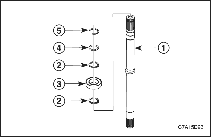


- Install the half shaft retainer (5),O-ring (4) and front wheel drive intermediate shaft bearing retainers (2) into the shaft (1).


Rear Output Drive Housing Assembly
Tools Required
DT-48075 Output Shaft Seal Installer
DT-48077 Output Shaft Slinger Installer
J-08614-A Pinion Flange Holder and Remover
J-29873 Injector Nozzle Socket (30mm)
J-5590 Pinion Bearing Race Installer-Rear
Disassembly Procedure
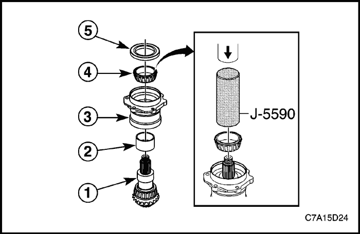
- Install the bearing spacer (2) to the transfer case rear output shaft (1).
- Using a press with J-5590,install the housing (3) and bearing (4) to the output shaft.
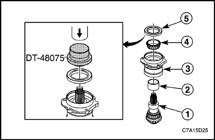


- Using a press with DT-48075, install the transfer case output shaft seal (5).
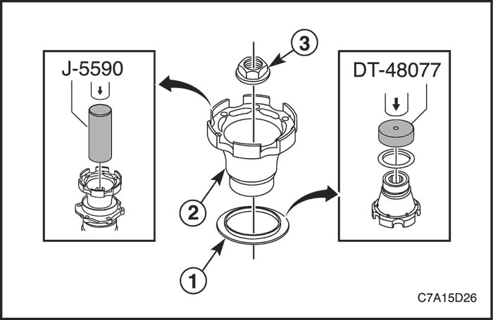


- Using a press with DT-48077, install the transfer case rear output shaft oil slinger (1) to the flange (2).
- Using a press with J-5590, install the transfer case rear output shaft flange (2).


- Install J-08614-A to the rear output shaft flange (2).
- Using a ratchet with the 30mm socket or J-29873, install the transfer case rear output drive gear nut (1).
Tighten
Tighten the transfer case rear output drive gear nut (1) to 235 N•m (173 lb-ft).
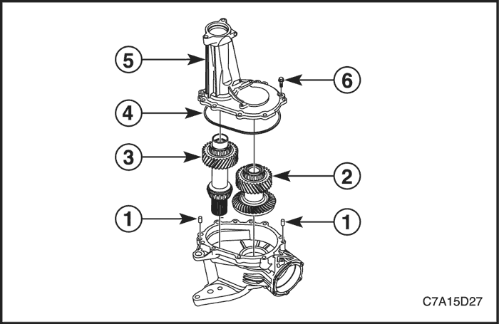


Transfer Case Assembly
Tools Required
J-25070 Heat Gun
DT-48076 Rock Guard Installer
DT-48094 Inner Drive Shaft Seal Protector
Assembly Procedure
- Install the transfer case half locating pins (1).
- Install the transfer case rear output drive shaft (2) and the transfer case input shaft (3) as a set with the splines engaged.
- Install the transfer case seal (4) to the transfer case (5).
- Install the 11 transfer case half bolts (6).
Tighten
Tighten the transfer case half bolts (6) to 29 N•m (21 lb-ft).
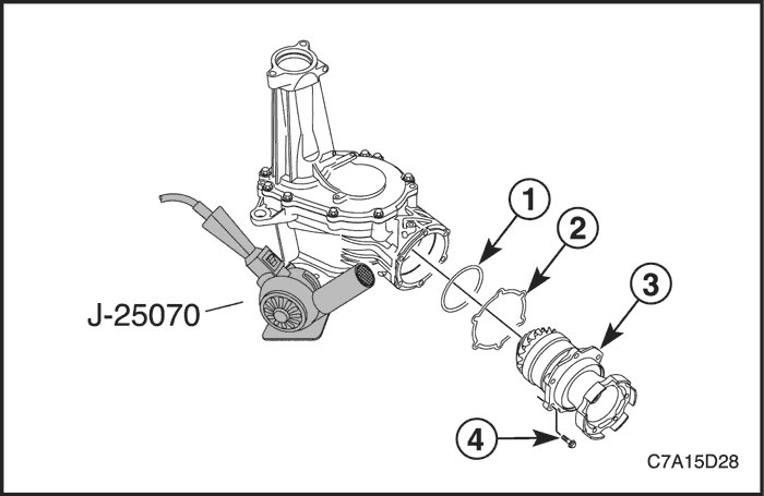


- Install the new transfer case rear output drive shaft housing seal O-ring (1).
- Install the transfer case rear output shim (2).
Important : Do not use a drive hammer when the splines are not engaged. Use of a drive hammer when the splines are not engaged will damage the drive output shaft teeth.
Important : Use of a heat gun allows easy alignment of the bolt holes to the housing during assembly.
- Heat the flange area of the drive housing with heat gun J-25070 for the easy installation of the transfer case rear output drive housing (3).
- Rotate the pinion gear during assembly to engage the gear teeth and install the rear output drive housing.
- Install the transfer case rear output drive shaft housing bolts (4).
Tighten
Tighten the transfer case rear output drive shaft housing bolts (4) to 29 N•m (21 lb-ft).
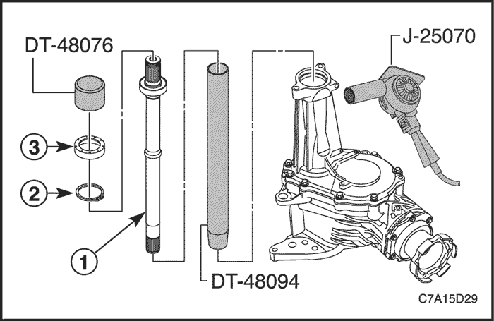


Important : Make sure that the length of intermediate shaft is different depending on the manual and automatic transaxle. Be sure to select the correct one. Otherwise, the wrong selection will make the intermediate shaft worn.
- Heat the end of transfer case housing with heat gun J-25070 for the easy installation of the front wheel drive intermediate shaft.
- Install the front wheel drive intermediate shaft (1) using DT-48094 in order to protect the intermediate shaft seal from damage.
- Install the front wheel drive retainer (2).
- Using rock guard installer DT-48076, Install the front wheel drive shaft shield (3).


- Install the transfer case O-ring seal (1).
- Install the transfer case drain plug (3).
Tighten
Tighten the transfer case drain plug (3) to 39 N•m (29 lb-ft).
- Fill the transfer case fluid thru the fill plug (2). Refer to "Transfer Case Fluid Replacement" in this section.
- Install the transfer case fill plug (2).
Tighten
Tighten the transfer case fill plug (2) to 39 N•m (29 lb-ft).
- Install the heat shield (4) and the transfer case heat shield bolts.
Tighten
Tighten the transfer case heat shield bolts to 11 N•m (97 lb-ft).


- Install the transfer case into the vehicle. Refer to "Transfer Case" in this section.
 | |  | |
| © Copyright Chevrolet Europe. All rights reserved |


