SECTION 9A
BODY WIRING SYSTEM
Caution : Disconnect the negative battery cable before removing or installing any electrical unit or when a tool or equipment could easily come in contact with exposed electrical terminals. Disconnecting this cable will help prevent personal injury and damage to the vehicle. The ignition must also be in LOCK unless otherwise noted.
SCHEMATIC AND ROUTING DIAGRAMS
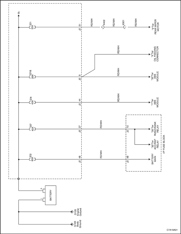
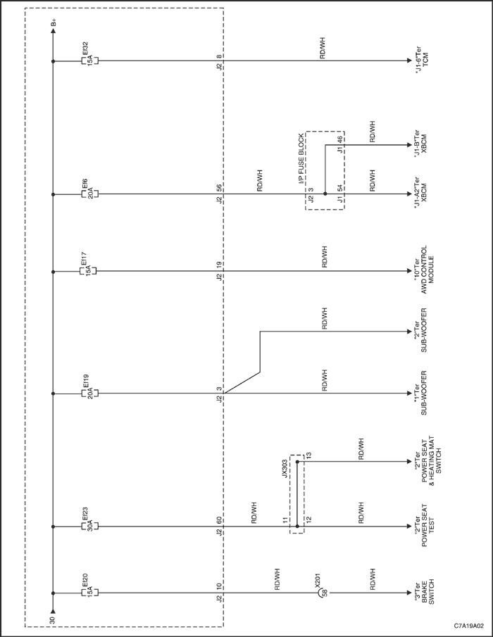
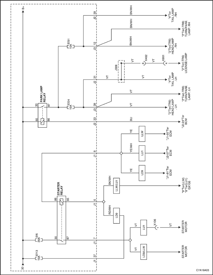
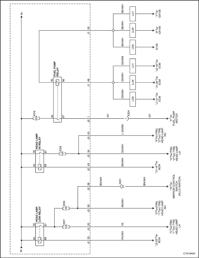
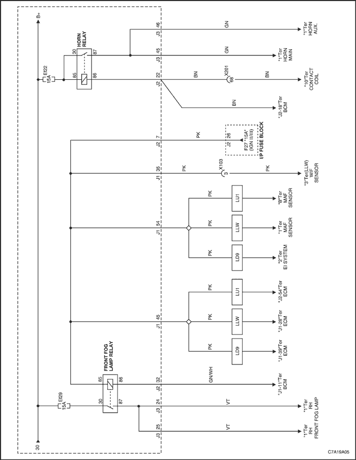
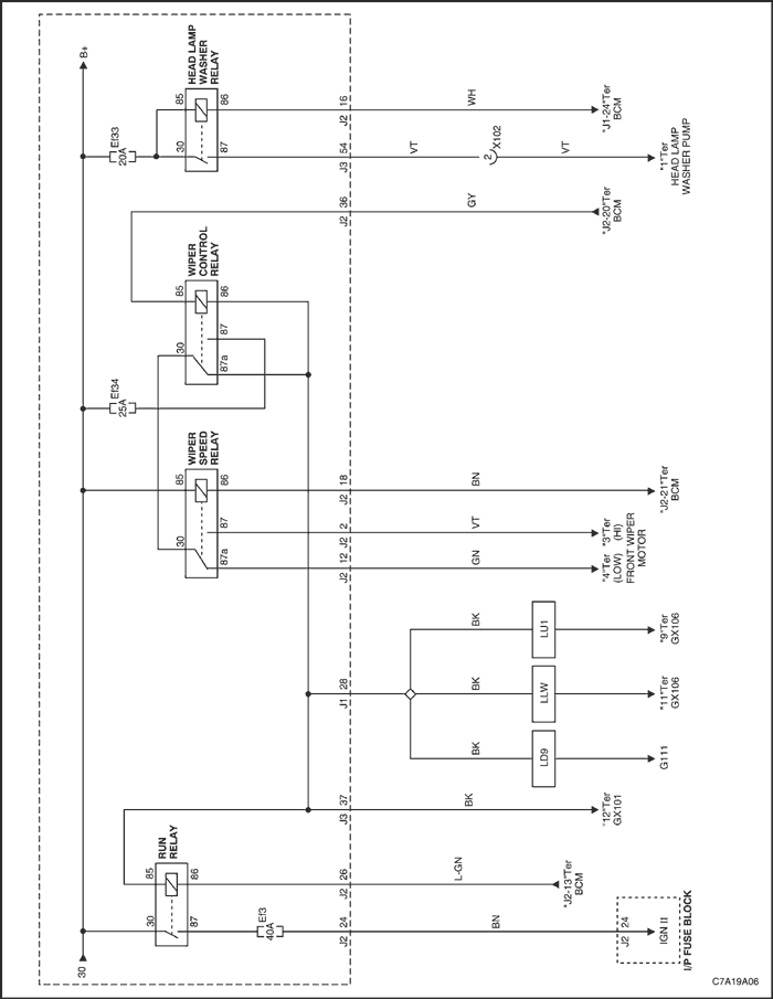
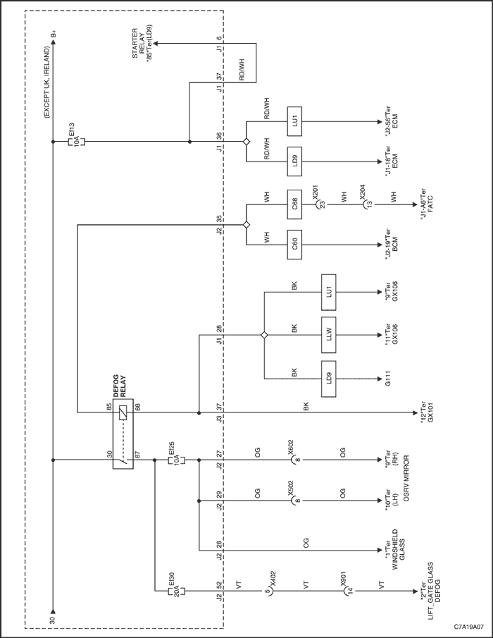
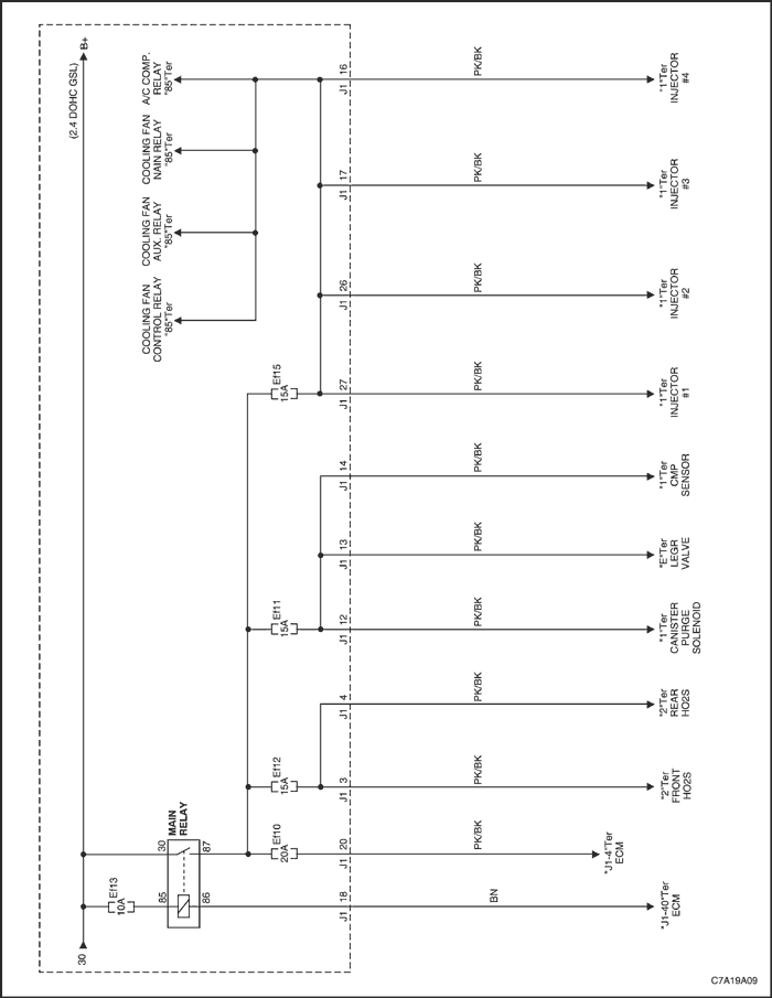
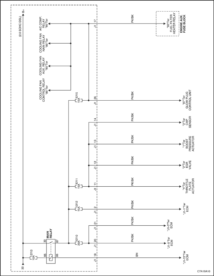
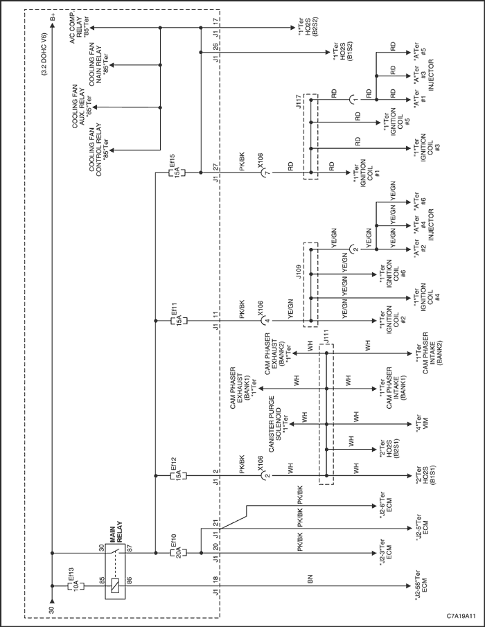
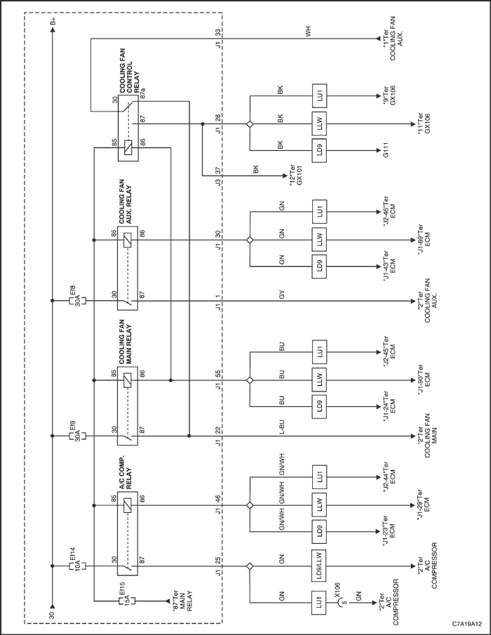
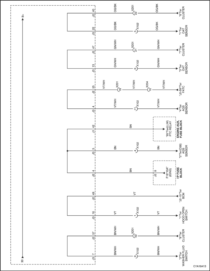
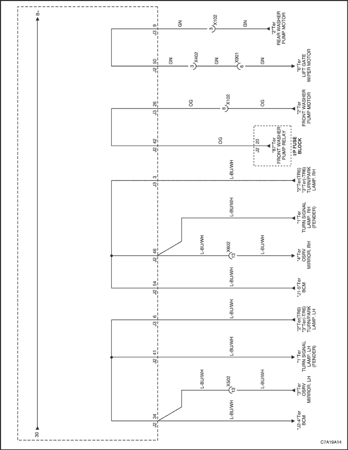
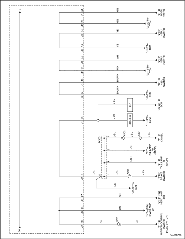
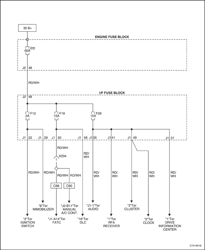
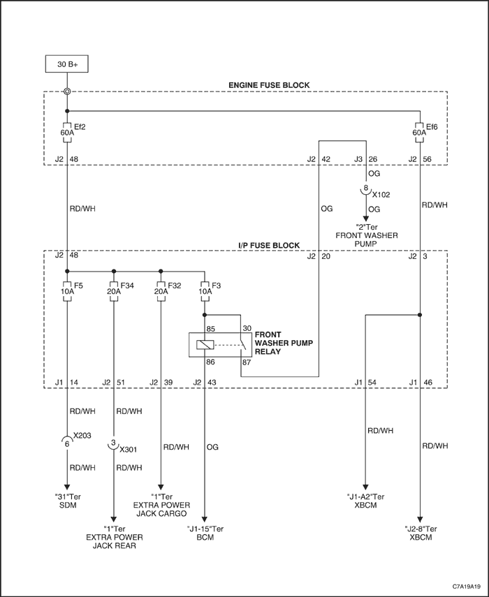
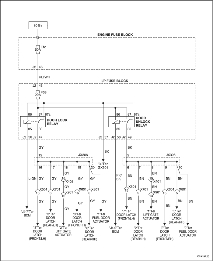
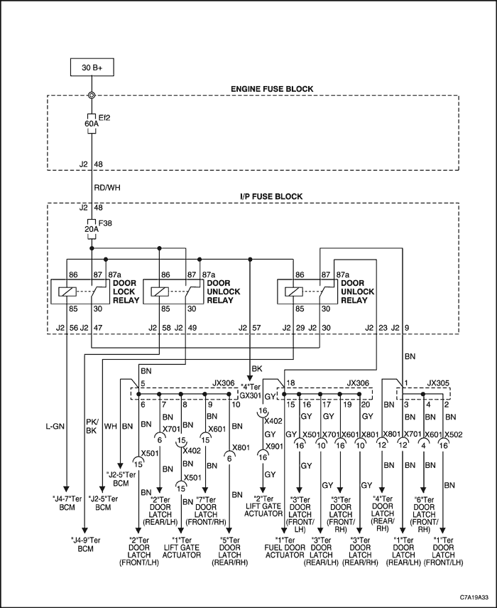
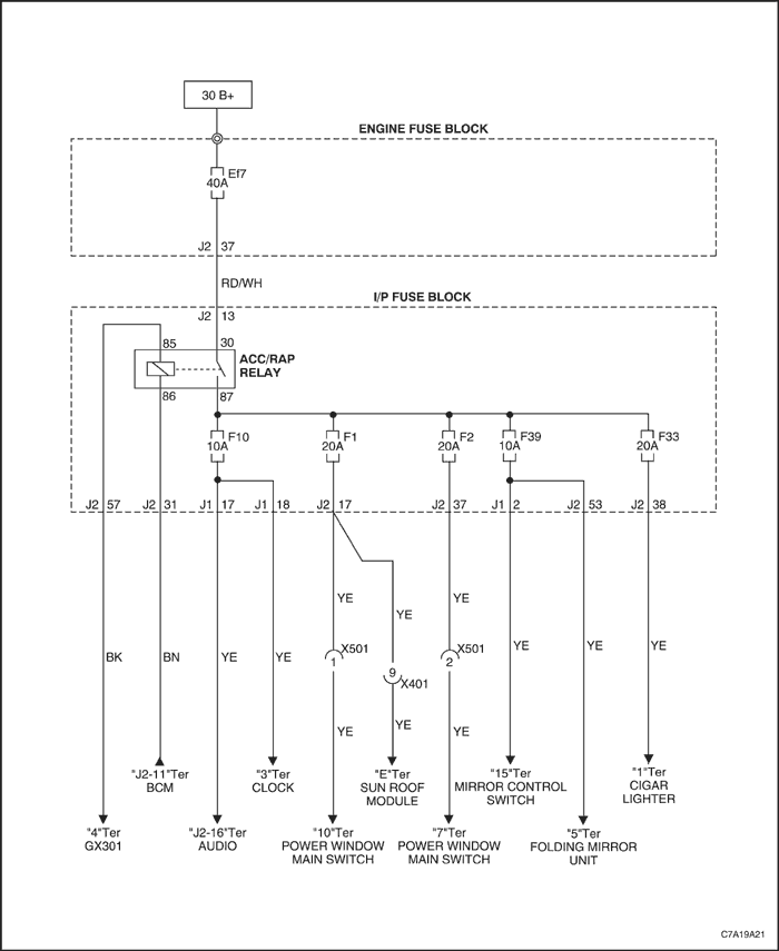
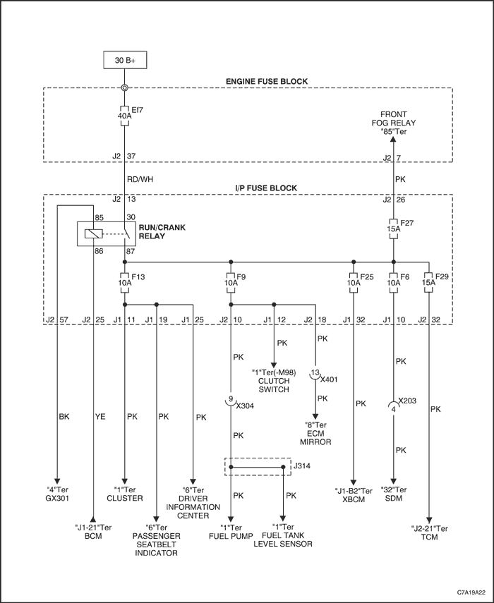
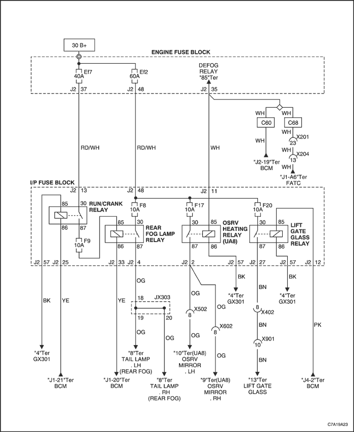
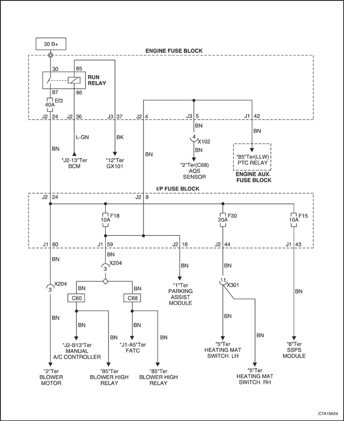
Power Distribution Schematic
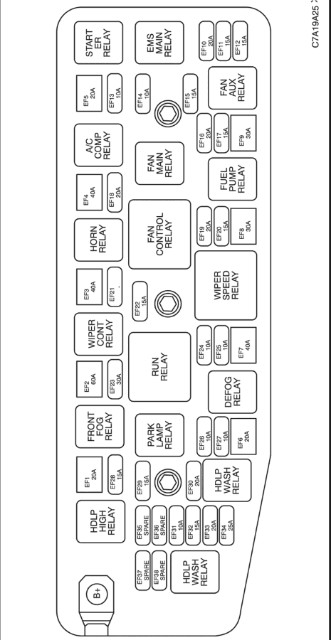
Fuse Block Locator (Engine)
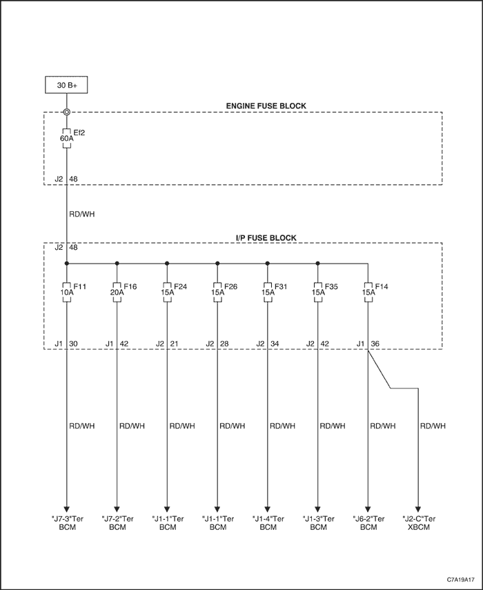
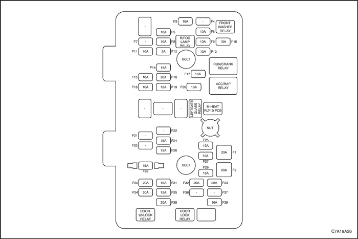
Fuse Block Locator (Passenger Compartment)
Fuse Chart (engine)
Power Supply | Fuse No. | Capacity | Usage |
30 B(+) | Ef1 | 20A | Rear Wiper Motor |
Ef2 | 60A | I/P Fuse Block(Battery Main) |
Ef3 | 40A | I/P Fuse Block(Ign II), Blower Motor |
Ef4 | 40A | ABS Module |
Ef5 | 20A | Starter Relay |
Ef6 | 20A | XBCM |
Ef7 | 40A | I/P Fuse Block (ACC/RAP Relay, Run/Crank Relay) |
Ef8 | 30A | Cooling Fan Aux |
Ef9 | 40A | Cooling Fan Main |
Main Relay | Ef10 | 20A | ECM |
. | . | Canister Purge Solenoid, LEGR Valve, CMP Sensor |
Ef11 | 15A | Throttle Plate Actuator, Boost Pressure Actuator, CMP Sensor |
. | . | Icnition Coil, Injector(#2,4.6) |
. | . | FRT HO2s, Rear HO2s |
Ef12 | 15A | ECM |
. | . | Ho2s, Vim, Cam Phaser Intake/Exhaust, Canister Purge Solenoid |
30 B(+) | Ef13 | 10A | Starter Relay, Main Relay |
Ef14 | 10A | A/C Comp. Relay |
Main Relay | . | . | LD9 : Injector, Cooling Fan (Aux., Main, Control), A/C Comp. Relay |
E15 | 15A | LLW : Glow Plug Control Unit, Cooling Fan(Aux., Main, Control), A/C Comp Relay, Engine Fuse Block Aux. |
. | . | LUL : Ignition Coil, Injector(#1,3,5), Cooling Fan(Aux., Main, Control), A/C Comp. Relay. |
30 B(+) | Ef16 | 20A | Fuel Pump Relay |
Ef17 | 15A | AWD Control Module |
Ef18 | 20A | ABS Module, Oil Feeding Conn. |
Ef19 | 20A | Sub-Woofer |
Ef20 | 15A | Brake Switch |
Ef21 | - | Not Used |
Ef22 | - | Not Used |
30 B(+) | Ef23 | 30A | Power Seat & Heating Mat Switch Power Seat Test Conn. |
Park Lamp Relay | Ef24 | 10A | Head Lamp LH, Tail Lamp LH, Turn/Park Lamp LH, License Lamp |
Degog Relay | Ef25 | 10A | Windshield Glass, Osrv Mirror |
Head Lamp Relay | Ef26 | 10A | Head Lamp RH, Mirror Control Switch |
Ef27 | 10A | Head Lamp LH |
Ef28 | 15A | Head Lamp LH/RH |
30 B(+) | Ef29 | 10A | FRT Fog Lamp Relay |
Degog Relay | Ef30 | 20A | Lift-Gate Glass Defog |
Park Lamp Relay | Ef31 | 10A | Head Lamp RH, Tail Lamp RH, Turn/Park Lamp RH |
30 B(+) | Ef32 | 15A | TCM |
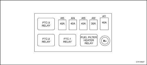
Fuse Chart (engine-aux)
Power Supply | Fuse No. | Capacity | Usage |
30 B(+) | Af1 | 60A | Glow Plug Control Unit |
30 B(+) | Af2 | 30A | Fuel Filter Heater Relay |
30 B(+) | Af3 | 40A | Ptc-1 Relay |
30 B(+) | Af4 | 40A | Ptc-2 Relay |
30 B(+) | Af5 | 40A | Ptc-3 Relay |
Fuse Chart (passenger compartment)
Power Supply | Fuse No. | Capacity | Usage |
Acc/Rap Relay | F1 | 20A | Power Window Main Swich, Sunroof Module |
F2 | 20A | Power Window Main Swich |
Ef2(60a) | F3 | 10A | FRT Washer Pump Relay |
Af4 | - | Not Used |
Ef2(60a) | F5 | 10A | SDM |
Ef2(60a) | F6 | 10A | SDM |
F7 | - | Not Used |
Ef2(60a) | F8 | 10A | Rear Fog Lamp Relay |
Run/Crank Relay | F9 | 10A | Rear Fog Lamp Relay, Fuelpump, Fuel Tank Level Sensor, ECM Mirror, Clutch Switch |
Acc/Rap Relay | F10 | 10A | Audio, Clock |
Ef2(60a) | F11 | 10A | BCM |
Ef2(60a) | F12 | 2A | Ignition Switch, Immobilizer. |
Run/Crank Relay | F13 | 10A | Cluster, Driver Information Center, Passenger Seatbelt Indicator |
Ef2(60a) | F14 | 15A | BCM, XBCM |
Ef3(40a) | F15 | 10A | SSPS Module |
Ef2(60a) | F16 | 20A | BCM |
Ef2(60a) | F17 | 10A | OSRV Heating Relay |
Ef3(40a) | F18 | 10A | Manual A/C Cont. , FATC, AQS Sensor, Blower High Relay, Park Assist Module, Engine Aux. Fuse Block(Ptc Relay) |
Ef2(60a) | F19 | 15A | Manual A/C Cont. , FATC, DLC |
Ef2(60a) | F20 | 10A | Lift Gate Glass Relay |
F21 | - | Not Used |
F22 | - | Not Used |
F23 | - | Not Used |
Ef2(60a) | F24 | 15A | BCM |
Run/Crank Relay | F25 | 10A | XBCM |
Ef2(60a) | F26 | 15A | BCM |
Run/Crank Relay | F27 | 15A | FRT Fog Relay |
Ef2(60a) | F28 | 15A | Cluster, Clock, Audio, RFA Receiver, Driver Information Center |
Run/Crank Relay | F29 | 15A | TCM |
Ef3(40a) | F30 | 20A | Heating Mat Switch |
Ef2(60a) | F31 | 15A | BCM |
Ef2(60a) | F32 | 20A | Extra Power Jack Cargo |
Acc/Rap Relay | F33 | 20A | Cigar Lighter |
Ef2(60a) | F34 | 20A | Extra Power Jack Cargo |
Ef2(60a) | F35 | 15A | BCM |
F36 | - | Not Used |
F37 | - | Not Used |
Ef2(60a) | F38 | 20A | Door Lock/Unlock Relay |
Acc/Rap Relay | F39 | 10A | Mirror Control Switch, Folding Mirror Unit |
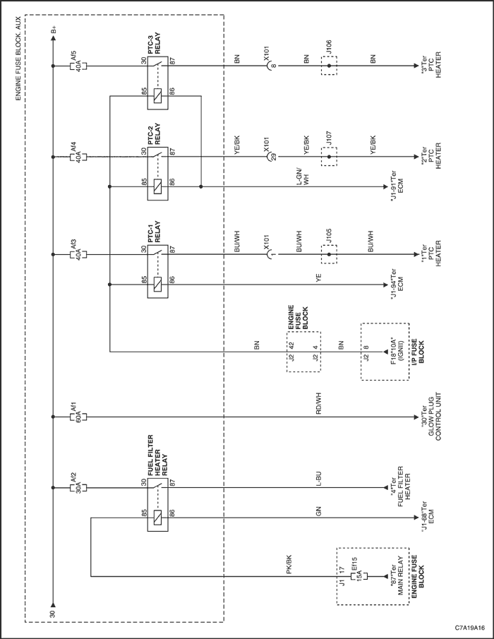
Engine Room Fuse Box. Aux (Diesel)
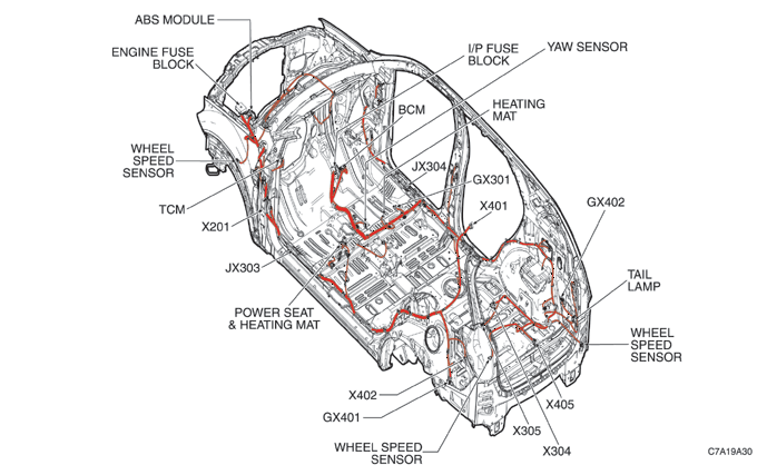
Rear Harness Routing
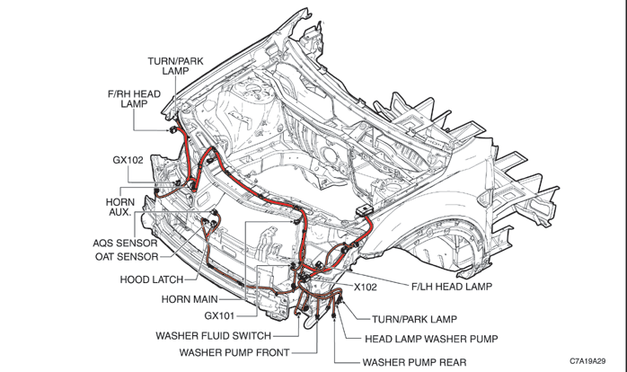
Front Harness Routing
Floor Harness Routing
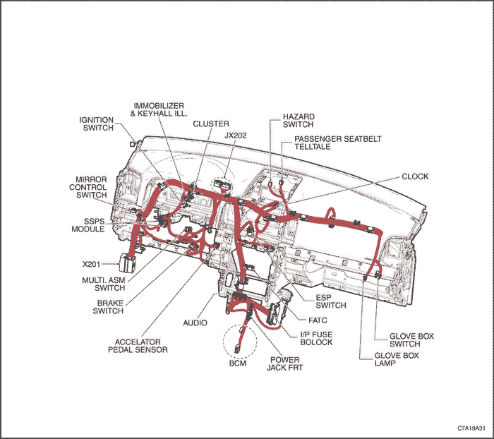
Instrument Harness Routing
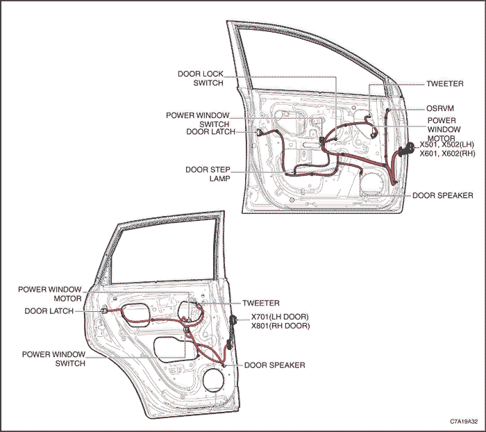
Door Harness Routing
DIAGNOSIS
Testing for Intermittent Conditions and Poor Connections
When the condition is not currently present, but is indicated in dtc history, the cause may be intermittent. an intermittent may also be the cause when there is a customer complaint, but the symptom cannot be duplicated. Refer to the symptom table of the system that is suspect of causing the condition before trying to locate an intermittent condition.most intermittent conditions are caused by faulty electrical connections or wiring. inspect for the following items:
- Wiring broken inside the insulation
- Poor connection between the male and female terminal at a connector
- Poor terminal to wire connection--some conditions which fall under this description are poor crimps, poor solder joints, crimping over the wire insulation rather than the wire itself, and corrosion in the wire to terminal contact area, etc.
- Pierced or damaged insulation can allow moisture to enter the wiring causing corrosion. the conductor can corrode inside the insulation, with little visible evidence. look for swollen and stiff sections of wire in the suspect circuits.
- Wiring which has been pinched, cut, or its insulation rubbed through may cause an intermittent open or short as the bare area touches other wiring or parts of the vehicle.
- Wiring that comes in contact with hot or exhaust components.
- Refer to inducing intermittent fault conditions in order to duplicate the conditions required, in order to verify the customer concern.
- Refer to testing for electrical intermittents for test procedures to detect intermittent open, high resistance, short to ground, and short to voltage conditions.
- Refer to scan tool snapshot procedure for advanced intermittent diagnosis and vehicle data recorder operation.
Testing for Proper Terminal Contact
It is important to test terminal contact at the component and any inline connectors before replacing a suspect component. Mating terminals must be inspected to ensure good terminal contact. A poor connection between the male and female terminal at a connector may be the result of contamination or deformation.
Contamination may be caused by the connector halves being improperly connected. a missing or damaged connector seal, damage to the connector itself, or exposing the terminals to moisture and dirt can also cause contamination. contamination, usually in the underhood or underbody connectors, leads to terminal corrosion, causing an open circuit or intermittently open circuit.
Deformation is caused by probing the mating side of a connector terminal without the proper adapter. other causes of terminal deformation are improperly joining the connector halves, or repeatedly separating and joining the connector halves. Deformation, usually to the female terminal contact tang, can result in poor terminal contact causing an open or intermittently open circuit.
Round Wire Connectors
It is important to test terminal contact at the component and any inline Follow the procedure below to test terminal contact of metri-pack or 56 series terminals.
Follow the procedure below in order to test terminal contact:
- Separate the connector halves.
- Visually inspect the connector halves for contamination. contamination may result in a white or green build-up within the connector body or between terminals. This causes high terminal resistance, intermittent contact, or an open circuit. an underhood or underbody connector that shows signs of contamination should be replaced in its entirety: terminals, seals, and connector body.
- Using an equivalent male terminal from the j-38125 , test that the retention force is significantly different between a good terminal and a suspect terminal. replace the female terminal in question.
Control Module/Component Voltage and Grounds
Poor Voltage or Ground Connections can Cause Widely Varying Symptoms
- Test all control module voltage supply circuits. Many vehicles have multiple circuits supplying voltage to a control module. Other components in the system may have separate voltage supply circuits that may also need to be tested. inspect connections at the module/component connectors, fuses, and any intermediate connections between the voltage source and the module/component. a test lamp or a dmm may indicate that voltage is present, but neither tests the ability of the circuit to carry sufficient current. Ensure that the circuit can carry the current necessary to operate the component.
- Test all control module ground and system ground circuits. The control module may have multiple ground circuits. Other components in the system may have separate grounds that may also need to be tested. Inspect grounds for clean and tight connections at the grounding point. Inspect the connections at the component and in splice packs, where applicable. Ensure that the circuit can carry the current necessary to operate the component.
Temperature Sensitivity
- An intermittent condition may occur when a component/connection reaches normal operating temperature. The condition may occur only when the component/connection is cold, or only when the component/connection is hot.
- Freeze frame, failure records, snapshot, or vehicle data recorder data may help with this type of intermittent condition, where applicable.
- If the intermittent is related to heat, review the data for a relationship with the following:
- High ambient temperatures
- Underhood/Engine generated heat
- Circuit generated heat due to a poor connection, or high electrical load
- Higher than normal load conditions, towing, etc.
- If the intermittent is related to cold, review the data for the following:
- Low ambient temperatures--in extremely low temperatures, ice may form in a connection or component. inspect for water intrusion.
- The condition only occurs on a cold start.
- The condition goes away when the vehicle warms up.
- Higher than normal load conditions, towing, etc.
- Information from the customer may help to determine if the trouble follows a pattern that is temperature related.
- If temperature is suspected of causing an intermittent fault condition, attempt to duplicate the condition.
Electromagnetic Interference (EMI) and Electrical Noise
Some electrical components/circuits are sensitive to electromagnetic interference (emi) or other types of electrical noise. Inspect for the following conditions:
- A misrouted harness that is too close to high voltage/high current devices such as secondary ignition components, motors, generator etc--these components may induce electrical noise on a circuit that could interfere with normal circuit operation.
- Electrical system interference caused by a malfunctioning relay, or a control module driven solenoid or switch-these conditions can cause a sharp electrical surge. normally, the condition will occur when the malfunctioning component is operating.
- Improper installation of non-factory or aftermarket add on accessories such as lights, 2-way radios, amplifiers, electric motors, remote starters, alarm systems, cell phones, etc-these accessories may lead to interference while in use, but do not fail when the accessories are not in use.
- Test for an open diode across the a/c compressor clutch and for other open diodes. some relays may contain a clamping diode.
- The generator may be allowing ac noise into the electrical system.
Incorrect Control Module
- There are only a few situations where reprogramming a control module is appropriate
- A new service control module is installed
- A control module from another vehicle is installed
- Revised software/calibration files have been released for this vehicle.
Important : Do not re-program the control module with the same software/calibration files that are already present in the control module. This is not an effective repair for any type of concern.
Verify that the control module contains the correct software/calibration. if incorrect programming is found, reprogram the control module with the most current software/calibration. refer to related module section for replacement, setup, and programming.
Diagnostic Repair Verification
- Install any components or connectors that have been removed or replaced during diagnosis.
- Perform any adjustment, programming or setup procedures that are required when a component or module is removed or replaced.
- Clear the dtcs.
- Turn off the ignition for 60 seconds.
- If the repair was related to a dtc, duplicate the conditions for running the dtc and use the freeze frame/failure records, if applicable, in order to verify the dtc does not reset. If the dtc resets or another dtc is present, refer to the related dtc code and perform the appropriate diagnostic procedure. Or if the repair was symptom related, duplicate the conditions under which the customer concern occurred to verify the repair. If the customer concern reoccurs, return to symptoms-vehicle and perform the appropriate symptom diagnostic.
- A new service control module is installed
- A control module from another vehicle is installed
- Revised software/calibration files have been released for this vehicle.
Important : Do not re-program the control module with the same software/calibration files that are already present in the control module. This is not an effective repair for any type of concern.
Verify that the control module contains the correct software/calibration. if incorrect programming is found, reprogram the control module with the most current software/calibration. refer to related module section for replacement, setup, and programming.